Basic Concepts of Analysis
The software uses the Finite Element Method (FEM). FEM is a numerical
technique for analyzing engineering designs. FEM is accepted as the standard
analysis method due to its generality and suitability for computer implementation.
FEM divides the model into many small pieces of simple shapes called elements
effectively replacing a complex problem by many simple problems that need
to be solved simultaneously.
|

|

|
|
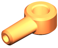
CAD model of a part |
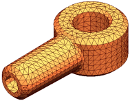
Model subdivided into small pieces (elements) |
Elements share common points called nodes.
The process of dividing the model into small pieces is called meshing.
The behavior of each element is well-known under all possible support
and load scenarios. The finite element method uses elements with different
shapes.
The response at any point in an element is interpolated from the response
at the element nodes. Each node is fully described by a number of parameters
depending on the analysis type and the element used. For example, the
temperature of a node fully describes its response in thermal analysis.
For structural analyses, the response of a node is described, in general,
by three translations and three rotations. These are called degrees of
freedom (DOFs). Analysis using FEM is called Finite Element Analysis (FEA).
|

|
|
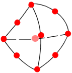
A tetrahedral element. Red dots
represent nodes. Edges of an element can be curved or straight |
The software formulates the equations governing the behavior of each
element taking into consideration its connectivity to other elements.
These equations relate the response to known material properties, restraints,
and loads.
Next, the program organizes the equations into a large set of simultaneous
algebraic equations and solves for the unknowns.
In stress analysis, for example, the solver finds the displacements
at each node and then the program calculates strains and finally stresses.
The software offers the following types of studies:
Static
(or Stress) Studies. Static studies calculate displacements, reaction
forces, strains, stresses, and factor of safety distribution. Material
fails at locations where stresses exceed a certain level. Factor of safety
calculations are based on one of four failure criterion.
Static studies can help you avoid failure
due to high stresses. A factor of safety less than unity indicates material
failure. Large factors of safety in a contiguous region indicate low stresses
and that you can probably remove some material from this region.
Frequency
Studies. A body disturbed from its rest position tends to vibrate at certain
frequencies called natural, or resonant frequencies. The lowest natural
frequency is called the fundamental frequency. For each natural frequency,
the body takes a certain shape called mode shape. Frequency analysis calculates
the natural frequencies and the associated mode shapes.
In theory, a body has an infinite number
of modes. In FEA, there are theoretically as many modes as degrees of
freedom (DOFs). In most cases, only a few modes are considered.
Excessive response occurs if a body is subjected
to a dynamic load vibrating at one of its natural frequencies. This phenomenon
is called resonance. For example, a car with an out-of-balance tire shakes
violently at a certain speed due to resonance. The shaking decreases or
disappears at other speeds. Another example is that a strong sound, like
the voice of an opera singer, can cause a glass to break.
Frequency analysis can help you avoid failure
due to excessive stresses caused by resonance. It also provides information
to solve dynamic response problems.
Linear dynamic studies are based on frequency
studies. The software calculates the response of the model by accumulating
the contribution of each mode to the loading environment. In most cases,
only the lower modes contribute significantly to the response. The contribution
of a mode depends on the load’s frequency content, magnitude, direction,
duration, and location.
The objectives of a dynamic analysis include:
(a) the design of structural and mechanical
systems to perform without failure in dynamic environments, and (b) the
reduction of vibration effects.
Buckling
Studies. Buckling refers to sudden large displacements due to axial loads.
Slender structures subject to axial loads can fail due to buckling at
load levels lower than those required to cause material failure. Buckling
can occur in different modes under the effect of different load levels.
In many cases, only the lowest buckling load is of interest.
Buckling studies can help you avoid failure
due to buckling.
Thermal
Studies. Thermal studies calculate temperatures, temperature gradients,
and heat flow based on heat generation, conduction, convection, and radiation
conditions. Thermal studies can help you avoid undesirable thermal conditions
like overheating and melting.
Design
Studies. Optimization design studies
automate the search for the optimum design based on a geometric design.
The software is equipped with a technology to quickly detect trends and
identify the optimum solution using the least number of runs. Optimization
design studies require the definition of the following:
Goals or
Objectives. State the objective of the study. For example, minimum
material to be used.
Design Variables.
Select the dimensions that can change and set their ranges. For example,
the diameter of a hole can vary from 0.5” to 1.0” while the extrusion
of a sketch can vary from 2.0” to 3.0”.
Constraints.
Set the conditions that the optimum design must satisfy. For example,
you can require that a stress component does not exceed a certain value
and the natural frequency to be within a specified range.
NOTE:
For the non-optimization design study, do not define any goals.
Nonlinear
Studies. When the assumptions
of linear static analysis do not apply, you can use nonlinear studies
to solve the problem. The main sources of nonlinearity are: large displacements,
nonlinear material properties, and contact. Nonlinear studies calculate
displacements, reaction forces, strains, and stresses at incrementally
varying levels of loads and restraints. When inertia and damping forces
can not be ignored, you can use nonlinear dynamic analysis.
 Nonlinear studies refer to
nonlinear structural studies. For thermal studies, the software automatically
solves a linear or nonlinear problem based on material properties and
thermal restraints and loads.
Solving a nonlinear problem requires much
more time and resources than solving a similar linear static study.
The principle of superposition does not apply
for nonlinear studies. For example, If applying force F1 causes stress
S1 and applying force F2 causes stress S2 at a point, then applying the
forces together does NOT necessarily cause a stress (S1+S2) at the point
as is the case for linear studies.
Nonlinear studies can help you assess the
behavior of the design beyond the limitations of static and buckling studies.
 Static studies offer a nonlinear
solution for contact problems when you activate the large displacement
option.
Drop Test
Studies. Drop test studies evaluate the effect of dropping the design
on a rigid floor. You can specify the dropping distance or the velocity
at the time of impact in addition to gravity. The program solves a dynamic
problem as a function of time using explicit integration methods. Explicit
methods are fast but require the use of small time increments. Due to
the large amount of information the analysis can generate, the program
saves results at certain instants and locations as instructed before running
the analysis.
After the analysis is completed, you can
plot and graph displacements, velocities, accelerations, strains, and
stresses.
Fatigue
Studies. Repeated loading weakens objects over time even when the induced
stresses are considerably less than allowable stress limits. The number
of cycles required for fatigue failure to occur at a location depends
on the material and the stress fluctuations. This information, for a certain
material, is provided by a curve called the S-N curve. The curve depicts
the number of cycles that cause failure for different stress levels. Fatigue
studies evaluate the consumed life of an object based on fatigue events
and S-N curves.