Hole Callouts
The Hole
Callout tool adds driven diameter dimensions to holes created by
the Hole
Wizard or circular cut features.
Hole callouts are available in drawings. If you change a hole dimension
in the model, the callout updates automatically.
Hole callouts use Hole Wizard information when you create a hole with
the Hole Wizard. The default formats for the Hole Wizard types are stored
in <install_dir>\solidworks\lang\<language>\calloutformat.txt.
A second file, calloutformat_2.txt,
is a simplified version. You can edit either file.
If you want to use the second file, you must rename the file to calloutformat.txt, which is the file
name the SolidWorks software references. You can set the location of the
default folder for Hole Callout Format
File in Tools, Options,
System Options, File Locations.
The number of instances is included
in the hole callout if a hole in a linear or circular pattern was created
in the Hole Wizard. In the JIS standard, you can change the number of
instances indicator to "x" or "-".
Hole callout examples:
|
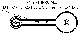
A hole callout using information
from the Hole Wizard:
|
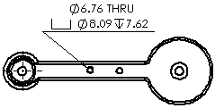
The same hole callout, but defined
by geometry:
|
|
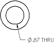
A cut feature representing a
hole. The cut feature must contain a circular sketch:
|
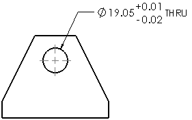
You can add tolerances and precision
to hole callouts:
|
 The axis of the hole must be normal to the
drawing sheet.
To add hole callouts in a drawing:
-
Click Hole Callout  on the Annotation toolbar, or click Insert, Annotations,
Hole Callout.
The pointer changes to  .
.
-
Click the edge of a hole, then click in the graphics area to place
the hole callout.
A Hole Callout is inserted
and the Dimension
PropertyManager appears. The callout contains a diameter symbol
 and the dimension of the hole diameter. If the depth
of the hole is known, the callout also contains a depth symbol
  and the dimension of the depth. If the hole is created in
the Hole Wizard, the callout contains
additional information (the dimensions of a countersink or number of hole
instances, for example).
-
Edit the callout in the Dimension
PropertyManager.
You can specify precision, select an arrow style, or add text. However,
you should retain the dimensions and symbols for the size and type of
hole.
If the hole has been created
by the Hole Wizard, you can also click Variables
in the Dimension PropertyManager
to access a list of Callout
Variables
to insert into the hole callout.
 If you attach a hole callout to a tapped
hole in ANSI inch standard and the current drawing units are millimeters,
the drill diameter and hole depths are reported in mm but the thread description
retains the ANSI inch size designation. You might want to replace the
thread description with other variables from the Callout
Variables dialog box.
Repeat steps 2 through 4 to insert additional
hole callouts, then click OK  .
.
You can
display the dimension in various formats by right-clicking the dimension
and clicking Display Options,
then clicking an option: Display as Diameter,
Display as Radius, Display
as Linear, Show Parentheses,
or Show as Inspection.
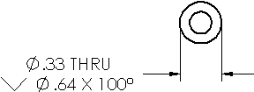
To edit the properties of a hole callout:
Select the callout and make the changes in the Dimension
PropertyManager.
 If you manually change a portion of the
callout text, you might break that portion's link with the model. SolidWorks
displays a warning message if you are about to break a link.
To modify hole callouts to include
tolerances:
Select
a hole callout.
In the
PropertyManager, select a Tolerance Type
 .
.
Type a
value for Maximum Variation  and Minimum Variation
 as necessary.
Click OK  .
.
Define by Geometry or Hole Wizard
To toggle between Hole Wizard and geometry definitions:
Right-click the hole callout and select Display Options, Define
by Geometry.
-
To return to the Hole Wizard definition, right-click the hole callout
and select Display Options, Define by Hole Wizard.
 These menu items are available only when
holes have been created using the Hole Wizard.
Instances indicators
You can change the number of instances indicator to a dash or "x"
for the JIS standard only.
|
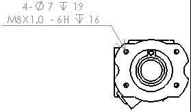
Dash indicator |
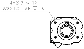
X indicator |
To change the number of instances indicator:
Open calloutformat.txt
in a text editor. The file is usually located in <install_dir>\solidworks\lang\<language>.
In the file:
At the top of the file, make sure NO-NUMBER-OF-INSTANCES
has an asterisk (*) in front of it.
Search for the JIS section. At the beginning
of the section, set JIS-COUNT-DELIMITER
to a dash or "x":
Save and close the file.
Make sure the calloutformat.txt
file is referenced by the Hole Callout
Format File in File
Locations.
Manually Define Standards
To manually define derived hole callout standards:
Edit the file calloutformat.txt
or calloutformat_2.txt located
in installation directory\solidworks\lang\<language>\.
Copy and paste the content for ANSI (or any default
standard) to a new section in the text file.
Using only upper case letters, rename the standard
name to your required derived hole callout standard.
Save the file as calloutformat.txt.
 Use only upper case letters
to define hole callout standards.
Modify the Hole Callout Format
You can modify the hole callout
format by editing the hole callout format definition file, calloutformat.txt.
Below is an example for editing
calloutformat.txt.
|
Using the code of the symbol
library, you can position symbols and order them in the definition of
each hole wizard type. For example, <MOD-DIAM> creates a diameter
symbol. The
end of the file contains text descriptions of the variables (see the sample
at the right). |
calloutformat.txt:
*Valid Hole
Wizard variables are as follows:
|
*VARIABLE
*<hw-type>
*<hw-std>
*<hw-fsttyp>
*<hw-fstsze>
*
*<hw-cbdepth>
*<hw-cbdia>
*<hw-cdrlang>
*<hw-cdrldepth>
*<hw-cdrldia>
*<hw-csang> |
DESCRIPTION*
Type
Standard
Fastener Type
Fastener Size
Counterbore Depth
Counterbore Diameter
Counterdrill Angle
Counterdrill Depth
Counterdrill Diameter
Countersink Angle
|
|
|
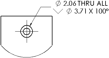
To use the definition file, locate the type of hole you want. |
Definition of a countersunk through hole:
|
COUNTERSINK-THRU=<MOD-DIAM> <hw-thruholedia> <hw-thru>;\
<HOLE-SINK><MOD-DIAM> <hw-csdia> X <hw-csang> |
|
|
|
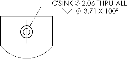
Modify the definition. |
In this example, the text C'SINK and a space are added before the <MOD-DIAM>
symbol:
|
COUNTERSINK-THRU=C'SINK <MOD-DIAM> <hw-thruholedia> <hw-thru>;\
<HOLE-SINK><MOD-DIAM> <hw-csdia> X <hw-csang> |
|
|
Related Topics
Adding Multi-jog Leaders to Hole
Callouts