Measure
Measures distance, angle, radius, and size of and between lines, points, surfaces, and planes in sketches, 3D models, assemblies, or drawings. When you select a vertex or sketch point, the x, y, and z coordinates are displayed.
 When the Measure tool is not active, commonly-used measurements for selected entities appear in the
status bar
.
To use the measure tool:
-
Click Measure  (Tools toolbar) or Tools, Measure.
 While the Measure dialog box is in place, you can switch among different documents without closing the dialog box. If you activate a document that has items already selected, the measurement information updates automatically.
-
Set options as described below.
-
Select the items to measure.
Callouts appear in the graphics area. New measurements update dynamically when you change selections.
 Click
Click  to expand the dialog box to display values.
|

|

|
|
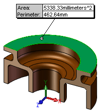
If you select a single entity, the size of the entity (the length of an edge, the area of a face, and so on) is displayed.
|
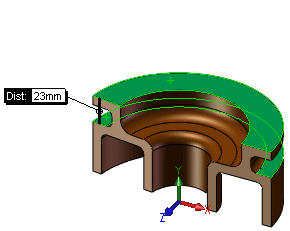
If you select two entities, the smallest distance between the entities is displayed.
|
|

|
-
To clear an item from the current selections, click the item again in the graphics area.
-
To clear all selections, click a blank area in the graphics area.
-
To temporarily turn off the measure function, right-click in the graphics area, and choose Select.
-
To turn the measure function back on, click inside the Measure dialog box.
|
Options
Arc/Circle Measurements  . Select to specify the distance to display when arcs or circles are selected:
-
Center to Center 
-
Minimum Distance 
-
Maximum Distance 
Units/Precision  . Select to specify custom measurement units and precision.
Show XYZ Measurements  . Select to display dX, dY, and dZ measurements between selected entities in the graphics area. Clear to display only the minimum distance between selected entities.
XYZ Relative To  . Select a coordinate system:
Projected On  . Display the distance between selected entities as projected on one of the following:
-
None  . Projection and Normal are not calculated.
-
Screen  .
.
-
Select Face/Plane  . The software calculates the projected distance (on the plane you select), and the normal distance (normal to the plane you select). Projection and Normal appear in the Measure dialog box.
 In Detached drawings, if the model is not loaded, all measurements are reported as 2D projected data.