Flat Pattern
The Flat-Pattern1 feature is intended to be the last feature in the folded sheet metal part. All features before Flat-Pattern1 in the FeatureManager design tree appear in both the folded and flattened sheet metal part. All features after Flat-Pattern1 appear only in the flattened sheet metal part.
Improvements to flattening sheet metal parts make flattening succeed for complex shapes which previously failed. These improvements also provide better flattened geometry for certain corner treatments, lofted bends, and in some cases where cuts intersect bend regions.
You can update existing flat patterns created prior to SolidWorks 2011 to use the improved method. In the FeatureManager design tree, right-click Flat-Pattern1 and click Edit Feature. In the Flat-Pattern PropertyManager, under Parameters, select Recreate flat-pattern.
 You can create *.dxf files of sheet metal flat patterns without flattening the part.
Some items to note about the flat-pattern feature:
-
New features in folded part. When Flat-Pattern1 is suppressed, all features that you add to the part automatically appear before this feature in the FeatureManager design tree.
-
New features in flattened part. You flatten the entire sheet metal part by unsuppressing Flat-Pattern1. To add features to the flattened sheet metal part, you must first unsuppress Flat-Pattern1.
-
Reorder features. You cannot reorder sheet metal features to go below Flat-Pattern1 in the FeatureManager design tree. So, you cannot order a cut with the Normal cut option underneath Flat-Pattern1.
-
Modify parameters. You can modify the parameters of Flat-Pattern1 to control how the part bends, to enable or disable corner options, and to control the visibility of the bend region in the flattened sheet metal part. You can define a grain direction to use when calculating the bounding box for sheet metal parts. The software determines the smallest rectangle (bounding box) that aligns with the grain direction to fit the flat pattern.
-
Sketches. You can transform sketches and their locating dimensions from a folded state to a flattened state and back again. The sketch and locating dimensions are retained.
 If you insert a
3D annotation
in a sheet metal part, a Flat pattern annotation view is automatically created in the Annotations
  folder. When you select the Flat pattern annotation view, the Flatten
  tool is unavailable.
-
Multibody sheet metal parts. Flat patterns of all bodies appear at the end of the FeatureManager design tree. When you expand the representation of a body in the cut list, the body's flat pattern appears at the end of its feature list.
-
Self-intersecting parts. If a part cannot be flattened because it has self-intersecting geometry, a warning is displayed and the feature causing the problem is highlighted in the graphics area.
To modify the parameters of the Flat-Pattern1 feature:
-
Right-click Flat-Pattern1 in the FeatureManager design tree, and select Edit Feature  .
.
-
In the PropertyManager, under Parameters:
-
In the graphics area, select a face that does not move as a result of the feature for Fixed face  .
.
-
Select
to merge faces that are planar and coincident in the flat pattern.
When selected, no lines are shown in the bend regions.
-
Select
to straighten curved edges in the flat pattern.
-
Under Corner Options, select
to apply smooth edges in the flat pattern.
-
Under Grain Direction, click in Grain Direction, then select an edge or line in the graphics area.
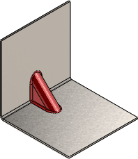
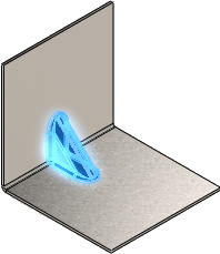
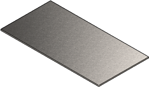
- Under Faces To Exclude, click in Faces To Exclude and select any faces in the graphics area that you do not want in the flat pattern. (You may want to exclude faces when the faces interfere with bends.) You must select the front and back of each face that you want to exclude.
|

|

|

|
|
Original part
|
Faces to exclude - select the front and back of each face
|
Flat pattern
|
-
Click OK  .
.
To display sketch dimensions in flattened state:
-
Create a sheet metal part that includes a sketch with dimensions on a face.

-
Flatten the model.
-
In the FeatureManager design tree, under Flat-Pattern  , expand Sketch Transformation
  .
.
-
Double-click the derived sketch to display the dimensions in a flattened state.
