After building your design in SolidWorks, you might need to answer questions like:
- Will the part break?
- How will it deform?
- Can I use less material without affecting performance?
Without simulation tools, these questions can be answered only by expensive and time-consuming product development cycles that typically include the following steps:
-
Build your model in the SolidWorks CAD system.
- Prototype the design.
- Test the prototype in the field.
- Evaluate the results of the field tests.
- Modify the design based on the field test results.
This process continues until a satisfactory solution is reached. Simulation can help you accomplish the following tasks:
- Reduce cost by testing your model using the computer rather than field tests.
- Reduce time to market by reducing the number of product development cycles.
- Optimize your designs by simulating concepts and scenarios before making final decisions.
Stress Analysis
Stress or static analysis calculates the displacements, strains, and stresses in a part based on material, fixtures, and loads. A material fails when the stress reaches a certain level. Different materials fail at different stress levels. SimulationXpress uses linear static analysis, based on the Finite Element Method, to calculate stresses. Linear static analysis makes several assumptions to calculate stresses in the part.
Finite Element Method
The Finite Element Method (FEM) is a reliable numerical technique for analyzing engineering designs. FEM replaces a complex problem with many simple problems. It divides the model into many small pieces of simple shapes called elements.
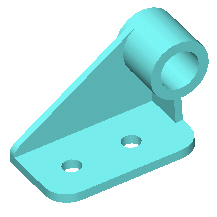 |
 |
| CAD model of a bracket |
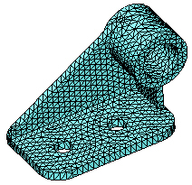
Model subdivided into small pieces (elements) |
Elements share common points called nodes. The behavior of these elements is well-known under all possible support and load scenarios. The motion of each node is fully described by translations in the X, Y, and Z directions, called degrees of freedom (DOFs). Analysis using FEM is called Finite Element Analysis (FEA).
 |
| A tetrahedral element. Red dots represent the element's nodes. Element edges can be curved or straight. |
SimulationXpress formulates the equations governing the behavior of each element taking into consideration its connectivity to other elements. These equations relate the displacements to known material properties, fixtures, and loads.
Next, SimulationXpress organizes the equations into a large set of simultaneous algebraic equations. The solver finds the displacements in the X, Y, and Z directions at each node.
Using the displacements, SimulationXpress calculates the strains in various directions. Finally, the program uses mathematical expressions to calculate stresses.