Expand IntroductionIntroduction
Expand AdministrationAdministration
Expand User InterfaceUser Interface
Expand SolidWorks FundamentalsSolidWorks Fundamentals
Expand Moving from 2D to 3DMoving from 2D to 3D
Expand AssembliesAssemblies
Expand CircuitWorksCircuitWorks
Expand ConfigurationsConfigurations
Expand SolidWorks CostingSolidWorks Costing
Expand Design CheckerDesign Checker
Expand Design Studies in SolidWorksDesign Studies in SolidWorks
Collapse Detailing and DrawingsDetailing and Drawings
Expand DFMXpressDFMXpress
Expand DriveWorksXpressDriveWorksXpress
Expand FloXpressFloXpress
Expand Import and ExportImport and Export
Expand Model DisplayModel Display
Expand Mold DesignMold Design
Expand Motion StudiesMotion Studies
Expand Parts and FeaturesParts and Features
Expand RoutingRouting
Expand Sheet MetalSheet Metal
Expand SimulationSimulation
Expand SimulationXpressSimulationXpress
Expand SketchingSketching
Expand Sustainability ProductsSustainability Products
Expand SolidWorks UtilitiesSolidWorks Utilities
Expand TolerancingTolerancing
Expand TolAnalystTolAnalyst
Expand ToolboxToolbox
Expand WeldmentsWeldments
Expand Workgroup PDMWorkgroup PDM
Expand TroubleshootingTroubleshooting
Glossary
Hide Table of Contents

Geometric Tolerance Properties

Specify the following properties when you create a geometric tolerance symbol.

To set geometric tolerance properties, do one of the following:

  • For parts, click Geometric Tolerance Tool_Geometric_Tolerance_DimXpert.gif (DimXpert toolbar) or Tools > DimXpert > Geometric Tolerance.
  • For drawings, click Geometric Tolerance Tool_Geometric_Tolerance_Annotation.gif (Annotation toolbar) or Insert > Annotations > Geometric Tolerance.

Symbol

Select a symbol.


gtol_symbol.gif
gtol_straightness.gif gtol_flatness.gif gtol_circularity.gif gtol_cylindricity.gif gtol_profile_of_line.gif
Straightness Flatness Circularity Cylindricity Profile of Line
gtol_profile_of_surface.gif gtol_parallel.gif gtol_perpendicular2.gif gtol_angularity.gif gtol_circular_runout.gif
Profile of Surface Parallel Perpendicular Angularity Circular Runout
gtol_total_runout.gif gtol_position.gif gtol_concentricity.gif gtol_symmetry.gif  
Total Runout Position Concentricity Symmetry None

Material Conditions

Select a material condition. The pointer must be in a Tolerance or Primary, Secondary, or Tertiary box to insert a material condition.

Only the material conditions that are appropriate for the selected symbol are available.

gtol_material_condition.gif
gtol_diameter.gif gtol_spherical_diameter.gif gtol_mmc.gif
Diameter Spherical Diameter Maximum Material Condition
gtol_lmc.gif gtol_rfs.gif gtol_tangent_plane.gif
Least Material Condition Regardless of Feature Size Tangent Plane
gtol_free_state.gif gtol_statistical.gif gtol_proj_tol.gif
Free State Statistical Projected Tolerance
gtol_square.gif gtol_UDP.gif Drawing_detailing_geometric_tolerance_Translation
Square Unequally Disposed Profile Translation

Height

If you click Projected Tolerance gtol_ptz.gif, enter a projected tolerance zone (PTZ) in Height.


gtol_height.gif

Tolerances

Type tolerance values for Tolerance 1 and Tolerance 2.


gtol_tolerances.gif

Unit Basis Tolerance

You can apply flatness and straightness tolerances on a unit basis. You apply a unit basis tolerance by following the tolerance value with a forward slash (/) and entering the per-unit area or per-unit length criteria.


DimX_UnitBasisTol_PropsDbox.gif

Primary, Secondary, and Tertiary

Enter datum names and material condition symbols for the Primary, Secondary, and Tertiary datums.

gtol_abc.gif

Frames

Create additional frames. You can set as many frames as needed. Use the Frames box to move among frames. You can see only two frames in the dialog box at a time.


gtol_2frames.gif

Composite Frame

Combines the symbols of two frames.


gtol_composite.gif

Below Frame

Add text below the feature control frame.
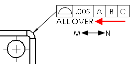

geo-tol-below-frame-text.png

Between Two Points

Type the labels of the points if the tolerance value applies between two points or entities.


gtol_between_two_points.gif


Provide feedback on this topic

SOLIDWORKS welcomes your feedback concerning the presentation, accuracy, and thoroughness of the documentation. Use the form below to send your comments and suggestions about this topic directly to our documentation team. The documentation team cannot answer technical support questions. Click here for information about technical support.

* Required

 
*Email:  
Subject:   Feedback on Help Topics
Page:   Geometric Tolerance Properties
*Comment:  
*   I acknowledge I have read and I hereby accept the privacy policy under which my Personal Data will be used by Dassault Systèmes

Print Topic

Select the scope of content to print:

x

We have detected you are using a browser version older than Internet Explorer 7. For optimized display, we suggest upgrading your browser to Internet Explorer 7 or newer.

 Never show this message again
x

Web Help Content Version: SOLIDWORKS 2014 SP05

To disable Web help from within SOLIDWORKS and use local help instead, click Help > Use SOLIDWORKS Web Help.

To report problems encountered with the Web help interface and search, contact your local support representative. To provide feedback on individual help topics, use the “Feedback on this topic” link on the individual topic page.