Hide Table of Contents

Bounding Boxes

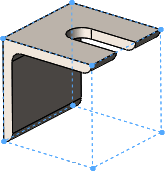
You can create a bounding box for any cut list item in a cut list, independent of the type of solid or sheet metal bodies in the cut list item.

The bounding box is represented by a 3D sketch and is based, by default, on the X-Y plane. Taking into consideration the bounding box's orientation, the bounding box is the smallest box in which the body fits.

weldment_bounding_box.png
Benefits of bounding boxes:
  • The overall dimensions of the bounding box appear in the Cut-List Properties dialog box so you can use them in a bill of materials, cut list, or other annotations.
  • With a bounding box, you can determine the length, width, and height of the stock needed for the body, which helps you to know how much space is required for packaging the product.
  • With weldments, you no longer have to find the stock size for plates manually.

Bounding Box Orientation

The orientation of a bounding box is based on one of the following:

  • The X-Y plane (default)
  • A preselected plane or planar face

Exceptions to these orientations are for weldment gussets and end caps:

  • For gussets, the orientation plane for the bounding box is parallel to the gusset faces.
  • For end caps, the orientation plane for the bounding box is parallel to the planar faces that they cap.
  • For a linear structural member, the orientation plane for the bounding box is perpendicular to the sketch line defining the member.
When you create bounding boxes for different cut list items, they can be oriented differently due to individual exceptions.

When you update a cut list, the existing orientation is used. When you edit a cut list or cut list item, the existing orientation is used unless you select a plane.

Working with Bounding Boxes

To create a bounding box:
  1. In the FeatureManager design tree, update the Cut list fm_cutlist_needs_update.png.
  2. Right-click the Cut list FM_CutList_Current.gif or a Cut-List-Item and click Create Bounding Box.
To edit a bounding box:
  • Right-click a Cut list FM_CutList_Current.gif or Cut-List-Item that already has a bounding box and click Edit Bounding Box to change the orientation plane or face in the PropertyManager.
To delete a bounding box:
  • Right-click a Cut list FM_CutList_Current.gif or Cut-List-Item and click Delete Bounding Box.
You cannot edit the actual 3D sketch.


Provide feedback on this topic

SOLIDWORKS welcomes your feedback concerning the presentation, accuracy, and thoroughness of the documentation. Use the form below to send your comments and suggestions about this topic directly to our documentation team. The documentation team cannot answer technical support questions. Click here for information about technical support.

* Required

 
*Email:  
Subject:   Feedback on Help Topics
Page:   Bounding Boxes
*Comment:  
*   I acknowledge I have read and I hereby accept the privacy policy under which my Personal Data will be used by Dassault Systèmes

Print Topic

Select the scope of content to print:

x

We have detected you are using a browser version older than Internet Explorer 7. For optimized display, we suggest upgrading your browser to Internet Explorer 7 or newer.

 Never show this message again
x

Web Help Content Version: SOLIDWORKS 2014 SP05

To disable Web help from within SOLIDWORKS and use local help instead, click Help > Use SOLIDWORKS Web Help.

To report problems encountered with the Web help interface and search, contact your local support representative. To provide feedback on individual help topics, use the “Feedback on this topic” link on the individual topic page.