This PropertyManager controls section views in part and assembly documents.
To open the Section View PropertyManager:
Click Section View  (View toolbar) or View > Display > Section View.
Drawing section view
The next available section view letter appears automatically. You can type to change it.
Section Method
| Planar |
Select Planar to define a section view by selecting one, two, or three planes or planar faces. |
| Zonal |
Select Zonal to define a section view by selecting one or more zones. Zones are defined by the intersection of the selected plane or face and the bounding box of the model. |
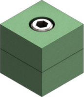
| Planar Section Method with 1 section plane selected |
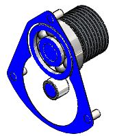 |
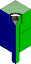
| Planar Section Method with 2 section planes selected |
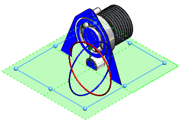 |
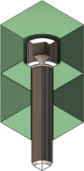
| Planar Section Method with 3 section planes selected |
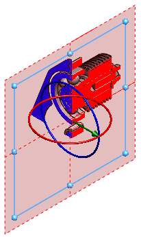 |
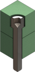
| Zonal Section Method |
 |
Section 1, Section 2, Section 3
Section 3 appears after you select Section 2. Use Section 2 and Section 3 to section the view with additional planes or faces.
| Section views hidden. |
|
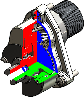
Show section cap selected and Keep cap color cleared. |
|
| Show section cap and Keep cap color cleared. |
|
Show section cap and Keep cap color selected. |
|
Selected bodies or components
| Selected bodies |
Select bodies in the graphics area or the flyout FeatureManager design tree to add them to Selected bodies. |
| Selected components |
Select components in the graphics area or the flyout FeatureManager design tree to add them to Selected components. |
| Components or bodies to include or exclude from the section view |
Lists components or bodies that you select from the graphics area or the flyout FeatureManager design tree. To delete all assemblies or parts, right-click, and select Clear Selections. To remove a body or component, select it in the graphics area or the FeatureManager design tree, or right-click it in the selection list box, and click Delete. |
| Exclude selected |
Available when you click Selected bodies or Selected components. The selected bodies or components are not sectioned. All other bodies or components are sectioned. |
| Include selected |
Available when you click Selected bodies or Selected components. The selected bodies or components are sectioned. Other bodies or components are not sectioned. |
| Enable selection plane |
Available when you click Selected bodies or Selected components. Shows a selection plane with the triad at the center of the plane. Use the triad to control the position and angle of the selection plane. |
Preview
Shows a graphics-only preview of the section results based on the section plane location and the components or bodies that you select in Selected components or Selected bodies. Hides the section planes, reference planes or faces outlines, and the selection plane.
Save
Click to save the section view, then set the following options in the Save As dialog box and click Save:
| View orientation |
Saves the section view as a named view in the Orientation dialog box. The view is not available in drawings. |
| Drawing annotation view |
Creates an annotation view for the section view and includes the section view on the View Palette in drawings. The name of the section view appears under Annotations  . .
When you save with this option, the Section Annotation View Props dialog box appears to let you specify components to leave uncut. Set the following options and click OK.
|
Excluded components
|
Select components to leave uncut in the graphics area or in the FeatureManager design tree. To remove a component from the list, select the component again, or select it in the Excluded components list and press Delete.
|
|
Auto hatching
|
Select to automatically adjust for neighboring components with the same crosshatch pattern. The hatch patterns alternate when sectioning an assembly.
|
|
Exclude fasteners
|
Select to exclude fasteners from being sectioned. Fasteners include any item inserted from SOLIDWORKS Toolbox (nuts, bolts, washers, and so on) except for structural members. You can also designate any component as a fastener.
|
To designate any component as a fastener, open the component and click . In the dialog box on the Custom tab, select IsFastener in Property Name, and type 1 for Value/Text Expression.
|
| View name |
Type a name for the section view. |