 |
Attached Radii |
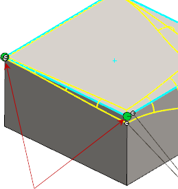
Lists the vertices of the edges selected under Items to Fillet for Edges, Faces, Features and Loops  , and lists control points you selected in the graphics area. , and lists control points you selected in the graphics area.
Vertices that connect to more than one filleted edge display in the list with *V. These vertices also display with a multi-edge control point in the graphics area. You can reverse the orientation of the fillet on one or more edges that intersect the vertex. Click the multi-edge control point to select which edges you want to reverse the orientation for.
 |
 |
Distance 1 |
Sets the radius for one fillet direction. |
 |
Distance 2 |
Sets the radius for the other fillet direction. |
| |
Set All |
Applies the current Distance 1 and Distance 2 to all items under Attached Radii .
|
 |
Reverse Direction |
Reverses the dimensions for Distance 1 and Distance 2 . |
| |
Profile |
Sets the profile type to fillet. The profile defines the cross sectional shape of the fillet.
|
Conic Rho 
|
Sets the ratio that defines the weight of the curve. Enter a value between 0 and 1.
|
|
 |
Number of Instances |
Sets the number of control points on the edges. |
| |
Smooth transition |
Creates a fillet that changes smoothly from one radius to another when matching a fillet edge to the adjacent face.
|
| |
Straight transition |
Creates a fillet that changes from one radius to another linearly without matching edge tangency with an adjacent fillet.
|