When you mesh a model, the software generates a mixture of solid, shell, spring, and contact elements based on the created geometry. The program automatically creates the following meshes:
| Solid Mesh |
The program creates a solid mesh with tetrahedral 3D solid elements for all solid components in the Parts folder. Tetrahedral elements are suitable for bulky objects. |
| Shell Mesh |
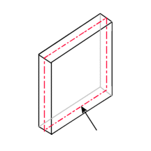
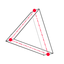
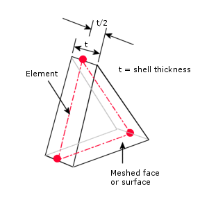
The program automatically creates a shell mesh for sheet-metals with uniform thicknesses (except drop test study) and surface geometries. For sheet metals the mesh is automatically created at the mid-surface. The program extracts the shell thickness from the thickness of the sheet metal.
 |
 |
| The mid-surface of a sheet metal is highlighted.
|
A shell element created at the mid-surface with the nodes shown.
|
For surfaces, the program locates the mesh on the surface (mid-plane of shell). You assign the thickness for the shell in the Shell Definition PropertyManager.

|
| Beam Mesh |
The program automatically uses beam mesh and identifies joints for touching or interfering structural members and non-touching structural members within a certain distance (tolerance). A beam element is a line element defined by two end points and a cross-section. Beam elements are capable of resisting axial, bending, shear, and torsional loads. Trusses resist axial loads only. When used with weldments, the software defines cross-sectional properties and detects joints.
|
| Mixed mesh |
The program automatically uses a mixed mesh when different geometries are present in the model. |