Form Tool Feature PropertyManager

The Form Tool Feature PropertyManager lets you set options for inserting forming tools in sheet metal parts.

To display this PropertyManager:

  • Drag a forming tool from the Design Library onto a sheet metal part.
  • In the FeatureManager design tree, right-click a forming tool and click Edit Feature .
    Forming tools inserted prior to SOLIDWORKS 2012 appear with a lock icon and are not accessible in the Form Tool Feature PropertyManager.

Type Tab

Placement Face

Placement Face Displays the face where the forming tool is inserted. You can select a different face in the graphics area.

Rotation Angle

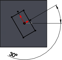
dim_ang_01.png Angle Lets you adjust the forming tool angle. Press Ctrl + the spin box arrows to adjust the forming tool in 45º increments.

You can edit the angle in the PropertyManager or when editing the profile sketch. The angle is located with respect to the default horizontal line in the placement sketch.

Edit the profile sketch by removing the angular dimension and adding relations to existing geometry. If you use this method, you can no longer change the angle in the PropertyManager. However, if you set the dimension as driven and do not make any other changes to the sketch, then, after setting the dimension back to driving, you can change the angle in the PropertyManager.
Do not edit the placement sketch by removing the horizontal relation from the line. This can cause the forming tool to have unexpected results.
Profile sketch of a lance forming tool with an angular dimension: forming_tool_profile_sketch.gif
  Flip Tool Reverses the direction of the cut.

Configuration

Form Tool Configuration Lets you select a configuration of the form tool part.
This Part Configuration Lets you select configurations of the target part. Click Configurations to select configurations. This is available when you edit an existing forming tool.

Link

Link to form tool Maintains a link between the forming tool you insert in the target part and the parent forming tool part. If you update the parent forming tool, the changes propagate to forming tools in target parts when you update the target parts.
Form tool Displays the forming tool part file location.
Replace tool Lets you browse to a different forming tool to replace the existing forming tool. This is available when you edit an existing forming tool.
Punch ID Displays the punch ID that is assigned to the forming tool. Punch IDs are displayed in drawings with punch tables.

Flat Pattern Visibility

You can choose how to display forming tools in flat patterns.

Override document settings Overrides the options set in Tools > Options > Document Properties > Sheet Metal.
Show Punch Displays the forming tool and its placement sketch.
forming_tool_show_punch.gif
Show Profile Displays the forming tool's placement sketch.
forming_tool_show_profile.gif
Show Center Displays the forming tool's center mark where the forming tool is located in the flat pattern.
forming_tool_show_center.gif

Position Tab

When you click the Position tab, you can click in the graphics area to insert additional instances of the forming tool. You can also use dimension and relation tools to set the forming tool placement.