Auto Dimension Scheme PropertyManager

To open the Auto Dimension Scheme PropertyManager:

Click Auto Dimension Scheme (MBD Dimension toolbar) or Tools > MBD Dimension > Auto Dimension Scheme.

Settings

Part type

Prismatic

When used with Geometric as Tolerance type, DimXpert applies position tolerances to locate holes and bosses.

For annotation views, size dimensions appear as callouts with open leaders


Note the difference in the geometric tolerances applied to the 30mm boss, and the annotation view used to depict them.

Turned

When used with Geometric as Tolerance type, DimXpert applies circular runout tolerances to locate holes and bosses.

For annotation views, size dimensions appear as linear dimensions, parallel to the axis.


Tolerance type Controls how features of size (hole types, slots, notches, widths, and cones), pockets, and surfaces are located relative to the datum or reference features.

Plus and Minus

DimXpert locates the features with linear plus and minus dimensions.

DimXpert does not apply dimensions to surface features in plus and minus mode.


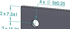
The main difference between Plus and Minus versus Geometric is how DimXpert controls the four-hole pattern, and how it applies tolerances to interrelate the datum features when in Geometric mode.

Geometric

DimXpert locates axial features with position and circular runout tolerances. Pockets and surfaces are located with surface profiles.

To show location dimensions, you must select Options > Document Properties > DimXpert > Geometric Tolerance , and then select Create basic dimensions.

Pattern Dimensioning Lets you apply linear or polar plus and minus dimension schemes.
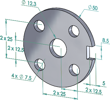
Linear

Locates all DimXpert features relative to the selected reference features, as applicable, using linear plus-minus dimensions.
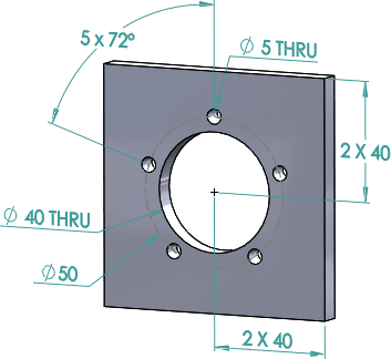
Polar

Apply to DimXpert pattern features that contain axial features that define a bolt circle.

Set the Minimum number of holes to recognize as a pattern.

Reference Features (for Plus and Minus) / Datum Selection (for Geometric)

Reference Features Select one to three reference features to use to generate linear plus and minus location dimensions. DimXpert validates reference features according to the rules defined for establishing datum reference frames, per ASME Y14.5.1M-1994. For example, selecting two planes that are parallel to one another generates an error.
Datum Selection Select the primary datum and optionally select the secondary and tertiary datums to use when generating geometric tolerances. DimXpert validates the datum set per ASME Y14.5.1M-1994.

Supported reference or datum features:

  • Boss
  • Cylinder
  • Simple Hole
  • Notch
  • Plane
  • Slot
  • Width
  • Cone

Scope

Controls which features DimXpert considers for dimensioning and tolerancing.
All features Applies dimensions and tolerances to the entire part. DimXpert considers all previously defined features, including those not listed under Feature Filters, as well as those features listed under Feature Filters.
This option is best suited for simple parts or parts for which all dimensions and tolerances are relative to a single datum reference frame or origin.
Selected features The objective is to dimension and tolerance the selected features.
This option is useful for more complex parts that have multiple datum schemes or require features to be dimensioned from different origins.

Feature Filters

Controls which features DimXpert recognizes and considers for dimensioning and tolerancing when you select All features under Scope.
  • Clearing features omits further recognition of those types. For example, if the part has no DimXpert dimensions or tolerances, and you clear Plane, DimXpert does not dimension or tolerance plane features, nor does DimXpert use the planar faces to derive a complex feature type such as a slot or notch. However, if there are pre-existing plane features in the part, DimXpert does consider them for dimensioning and tolerancing whether or not you select Plane.
  • Clearing features omits further recognition of those types as features or as pattern features, as applicable. For example, if you clear Simple hole, this prevents patterns of simple holes from being dimensioned and toleranced.
Check All Filters
Uncheck All Filters

Examples

The three mutually perpendicular planes is the most common example and provides a sound origin.
This plane and boss combination works well for these types of symmetrical turned parts.
You should base the order in which you select features on part function.

For example, given this two-part assembly, the functional requirements are:

Mate

The cover must seat (mate) against the recessed plane of the plate, making them flush.

Locate

The large outer diameter of the cover must be centered (located) with its corresponding diameter on the plate

Align

The small radius of the cover must be oriented (aligned) with the corresponding radius on the plate.

Given these parameters, when applying automatic dimension schemes to the cover, set the datums as follows:

Primary Datum (A)

Mating feature

Secondary Datum (B)

Locating feature

Tertiary Datum (C)

Aligning feature

These settings create the results shown.