Edge Flanges

You can add edge flanges to one or more edges.
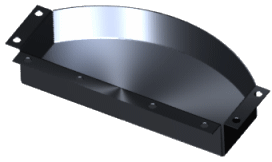
edge_flange_example.gif

General edge flange characteristics include:
  • Thickness is linked to the thickness of the sheet metal part.
  • Sketch line of the profile must lie on the selected edge.
For legacy parts opened with the SOLIDWORKS 2007 application, edge flange dimensions appear only after editing existing edge flanges,or rebuilding the part.

Linear

You can add flanges to one or more linear edges, as well as adjust angle, position, etc.

Example:
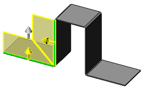
edge_flange_2_edges.gif

Curved Edges

You can add curved edge flanges to edge flanges created off a planar base.

Examples:
shm_planar_non-linear_flanges.gif shm_multi_planar_tangent_flanges.gif
Single curved edge Multiple tangent edges
shm_cylindrical_flange.gif shm_lofted_curved_edge.gif
Cylindrical Lofted
  • Curved edges must border a planar face.
  • Multiple edges must be tangent but can include linear and curved segments.
  • Specify No Relief or add relief using Custom Relief Type in the PropertyManager.
    shm_relief_example.gif shm_relief_no_relief.gif shm_relief_rectangle.gif
      No relief Relief Type: Rectangle
  • Default direction of the edge flange is normal to the base flange at the edge.
    edge_flange_curved_normal_shm.gif
  • Creating an edge flange along a non-planar edge adds a 3D sketch.
Limitations:
  • You cannot select additional edges that are not tangent to the original edges.
    edge_flange_curved_additional_shm.gif
  • Only certain bend positions are available for edge flanges created on the straight edge of lofted or cylindrical parts.