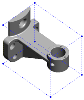
The dimensions of a
bounding box can help you determine the space required to ship and package
product.
Calculating a bounding box for a part with many faces can be time consuming.
If a part has many faces, create the bounding box after you finish modeling the
part.
To create a bounding box for a part and view its
properties:
-
In a part document, click .
-
In the Bounding Box PropertyManager,
select Best Fit. The orientation of the bounding box is
based on the X-Y plane.
The bounding box calculated by the SOLIDWORKS software might not have the
minimum volume for some bodies and parts. Use past experience and
experimental data to review the suggested bounding box, and modify it if
required.
To change the reference plane, click Custom
Plane.
-
Under Options, select the
following:
- Include hidden bodies
- Include surfaces
- Show Preview
If you hide a body in the part, the bounding box automatically updates and
only encloses the visible bodies in the model.
-
Click
 .
.
In the FeatureManager design tree, Bounding
Box
 is added after
Origin.
is added after
Origin.
You can right-click the bounding box and from the shortcut
menu, select Hide, Show,
Suppress, or
Unsuppress.
To view bounding box properties, hover over Bounding
Box in the FeatureManager design tree or click tab. Values for thickness, width, length, and volume of the bounding
box are listed.