Use a shell mesh for thin-walled parts with uniform thickness. A shell mesh is composed of triangular shell elements and it requires less computational time than a solid mesh without compromising the results accuracy.
To create a shell mesh, do one of the following:
- In the PlasticsManager tree
 , double-click Shell and click Auto or Manual, or
- Click the down arrow on Solid Mesh (Automatic) (Plastics CommandManager), and select Shell Mesh (Manual), or Shell Mesh (Automatic).
|
Automatic
|
The program selects the optimal size of the triangular shell element based on the part size. The shell mesh is created on the surface of the part leaving the core hollow. The program supports automatic meshing for a single body only.
|
|
Manual
|
You can set the size of the triangular shell element, and refine the mesh in selected regions. You set the surface mesh options in a step-by-step process, and use mesh editing tools to improve the quality of the mesh.
|
To convert an existing shell mesh to a solid mesh:
- In the PlasticsManager tree , double-click Solid and click Manual.
- Select Use Shell Mesh Data.
The software employs the shell mesh formulation on the surface of the part to fill in the volume with solid elements.
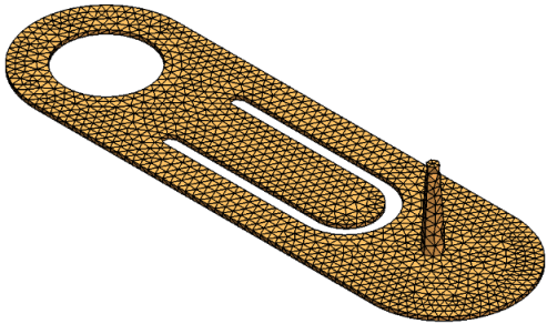 |
| Shell mesh created with Automatic option. |
 |
 |
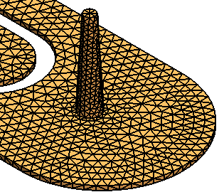
| Shell mesh created with Manual option and Local Refinement set to Automatic. A finer mesh is applied to smaller features. |
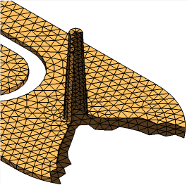
Section view of a shell mesh. All exterior surfaces of the part are meshed. The interior core is hollow. |