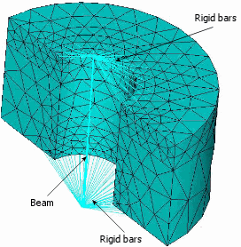
Simulation models a bolt connector in a spider-like arrangement with (a) a beam element to represent the bolt shank, and (b) rigid bar elements to represent the nut and head parts.
The beam element has no resistance to torque because the axial rotational degree of freedom is released. This formulation is consistent with the physical model. The applied preload (clamp force) provides the frictional force needed to resist slippage between the connecting parts.

The beam element that represents the bolt shank is tension-resistant only—no resistance to compressive force.
In loading scenarios where the bolts are under compressive forces, the axial forces of bolt connectors may not be accurate. In such cases, a decrease in preload bolt force can result in a "loosening" of the bolt and loss of contact between the bolt and the components. This behavior cannot be captured by the bolt connector formulation. For these cases, model the actual bolt and define no penetration contact sets between the bolt and the components.
For loose fit bolts, the number of rigid bar elements equals the number of nodes on the faces that are in contact with the nut and the head of the bolt. Simulation imprints the head or nut diameter on the faces of the connecting parts to define and mesh the head or nut area.
Like loose fit bolts, Simulation generates rigid bar elements for tight fit bolts. Additionally, Simulation generates rigid bar elements between the beam nodes and the cylindrical surface nodes that are in contact with the bolt shank.