 |
|
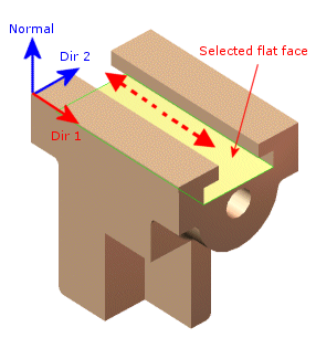
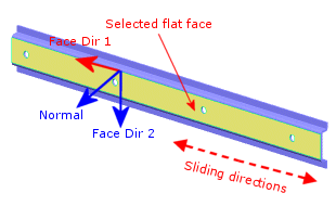
| The selected flat face (shown in yellow) can only slide along in the direction shown by dashed red arrows, for example, Dir 1 of the face. Setting the other two directions (Dir 2 and Normal) to zero enforces this condition.
|
 |
|
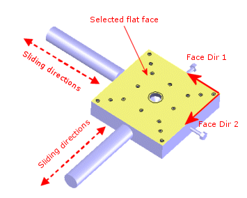
| The selected flat face (shown in yellow) can slide along Face Dir 1 and Face Dir 2. Setting the normal motion to zero enforces this condition.
|
 |
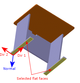 |
| The desk shown above is free to move on the ground (dashed red arrows) and no normal motion (solid blue arrow) is allowed.
|
The selected flat faces (shown in yellow) can slide freely along Dir 1 and Dir 2 of the selected faces and restrained in the Normal direction.
|
 |
 |
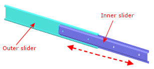
| The inner slider is free to slide along the directions shown in dash arrows.
|
Use the On flat face restraint type to specify zero displacements along Face Dir 2 and Normal to the face.
|