Distributed coupling
constrains the motion of the coupling nodes to the translation and rotation of the reference
node.
The distributed coupling constraint is enforced in an average sense in a
way that enables control of the transmission of loads and displacements through weight
factors at the coupling nodes. Distributed coupling allows the coupling nodes of the
selected geometry (face or edge) to move relative to each other.
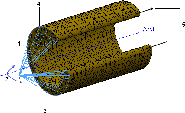 |
| Example of a Distributed Coupling Constraint |
| 1 |
Reference node |
| 2 |
Prescribed rotation |
| 3 |
Face that defines the coupling nodes |
| 4 |
Coupling nodes |
| 5 |
Warping (out of plane deformation) permitted by the
distributed coupling constraint |
Forces and moments at the reference node are distributed either as a
coupling node-force distribution only (default) or as a coupling node-force and moment
distribution. This constraint distributes loads such that the resultants of the forces
(and moments) at the coupling nodes are equivalent to the forces and moments at the
reference node.
For cases of more than a few coupling nodes, the distribution of remote
forces/moments and mass is not determined by equilibrium alone, and distributing weight
factors scale the distribution. These weighting factors are available when
Connection Type is
Distributed:
|
Default (constant)
|
Uniform weight distribution. All weight factors wi are equal to
1.
|
|
Linear
|
Weight factors decrease linearly with distance from the reference
node.
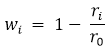
wi is the weight factor at coupling node i,
ri is the coupling node radial distance from the reference
node, and r0 is the distance to the furthest coupling node.
|
|
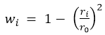
Quadratic
|
Weight factors decrease with distance from the reference node following a
quadratic polynomial formulation.
|
|
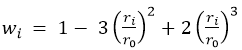
Cubic
|
Weight factors decrease with distance from the reference
node following a cubic polynomial formulation.
|
When Connection Type is Rigid, the coupling nodes do not move relative to
each other. Rigid bars connect the attachment point to the coupling nodes, and high
stresses can develop as a result. The faces where remote loads or displacements are
applied behave like rigid bodies.
The remote load and mass combinations supported for the
Distributed and
Rigid connections are listed below (Linear static and Nonlinear static
studies).
| Remote Load Combinations |
Distributed Connection |
Rigid Connection |
| Force and Moment |
Supported |
Supported |
| Translation and Rotation |
Supported |
Supported |
| Force, Moment, Translation, and
Rotation |
Supported |
Not supported |
| Force, Moment, and Mass |
Supported |
Supported |
| Translation, Rotation, and
Mass |
Supported |
Not supported |
| Force, Moment, Translation,
Rotation, and Mass |
Supported |
Not supported |
For Mass, you need to define Gravity (and perhaps Centrifugal load).