 |
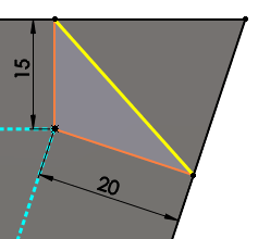
Angle Distance
|
Sets the Distance and Angle in the Chamfer PropertyManager or in the graphics area. A
handle appears that points in the direction in which the distance is
measured. Select the handle to flip the direction, or click
Flip direction.
|
 |
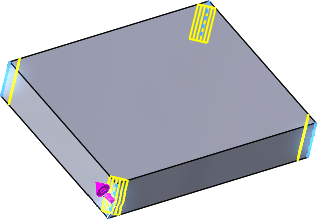
Distance Distance
|
Select edges or faces of solids. Under Chamfer Parameters, select a Chamfer Method to enter Asymmetric values for both distances on either side of the selected chamfer edges, or Symmetric to specify a single value.


|
 |
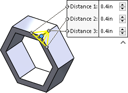
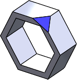
Vertex
|
Enter values for the three distances on each side of the selected vertex, or click Equal Distance and specify a single value.
|
 |
Offset Face
|
Offset face chamfers are solved by offsetting the faces next
to selected edges. The software calculates the intersection point of
the offset faces, then calculates the normal from that point to each
face to create the chamfer.This method yields
predictable results when chamfering between nonplanar faces.
Offset face chamfers can change direction on an edge-by-edge
basis, and they support chamfering entire features and surface
geometry.
 |
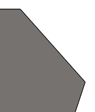
| Calculation
of chamfer offset |
 |
| Chamfer
applied |
|
 |
Face Face
|
Blends nonadjacent, noncontinuous faces. Face face chamfers
can create symmetric, asymmetric, hold line, and chord width
chamfers.
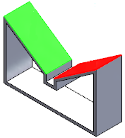 |
| Face Set 1 and
Face Set 2
selected |
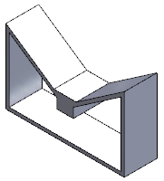 |
| Face face
chamfer app |
|