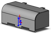
You can position forming tools on sheet metal using sketch tools.
To position forming tools:
-
On a face of a sheet metal part, sketch any entities such as construction lines to help position the forming tool using dimensions and relations.
- In the Task Pane, select the Design Library
 tab.
tab.
- Click
 in the title bar to pin the Design Library.
- Browse to forming tools, and select one of the folders.
The contents of the folder are previewed in the lower panel.
- Select a forming tool from the lower panel, drag it to the correct face, and release the pointer.
The forming tool is placed on the face and the Position form feature dialog box appears.

-
Use Smart Dimension
 , Add Relations
  , or Modify Sketch
  to position the forming tool on the face.
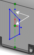
In this example, a Midpoint  relation was added between the construction line and the origin of the forming tool sketch.

Leave the Position form feature dialog box open while positioning the forming tool.
- Click Finish to set the forming tool and close the dialog box.