| |
Clamp Force
direction
|
Specify the Injection
Molding Machine opening direction to enable the software to estimate
the Clamp Force in that direction. This parameter is optional. If
you do not specify a Clamp Force direction, the software provides an
estimate of the Clamp Force in all three directions (X, Y, and Z).
To set the machine direction, select one of the default axis X, Y,
or Z, or select a plane, planar face, or linear edge of your model
(useful when the machine direction isn’t aligned with one of the
default axis). |
| |
Excluded Elements
|
If your model contains undercuts or slides, you can exclude these areas
(elements) from the Clamp Force estimation. Select the elements
of your model that represent the undercut or slide regions, and
click Apply. The elements are excluded
from the Clamp Force calculation when you run a Flow or Pack
simulation. For example, the red areas in the image below
represent undercuts, which can be excluded from the Clamp Force
estimation. 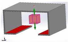 |
You can view the Clamp Force result:
- In an XY plot where the single Clamp
Force option replaces the default X, Y, or Z-direction
Clamp Force.
- In the Summary and
Report PropetyManager, the Clamp Force of
user-defined machine direction is listed at the top of
Flow and Pack summary.
|