Sometimes the geometry in or between your components appears to be accurate, but is slightly wrong.
For example, you can have the following situations:
- Two components that look parallel, but are positioned to be slightly diverging.
-
An imported block that appears to have orthogonal sides, but the angle between two faces is actually 90.1 degrees.
-
Two components that appear to be the same height, but are slightly different.
-
Bolt holes in two components that should be the same distance apart, however one component was made using rounded metric units, and one using rounded English units.
These design errors (and others) can sometimes lead to mating errors.
Example
Example
Suppose your intention is to align these two blocks so that they are coincident on one side and one end as shown. Your visual inspection makes you believe the blocks are each orthogonal.
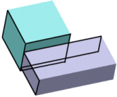
You first add a coincident mate between the sides:
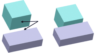
Then add a coincident mate between the ends:
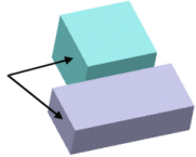
The blocks do not move into the mate and a mating error appears in the FeatureManager design tree.
How MateXpert helps
When you click on the problem mate in MateXpert, a message appears which tells you that the faces in the mate are not parallel, and lists the angle between the faces.
How you can fix the problem
Change the geometry of one of the blocks so that the faces are parallel. Because
your intention was for both blocks to be orthogonal, examine the blocks for the
cause of the non-orthogonal geometry. In this case, the sketch for the base
extrusion of one of the blocks was not a rectangle. You do not have to delete the
problem mate. After you correct the geometry in your parts, the mate will be
satisfied.
You can also use mate callouts and
View Mate Errors to help identify and resolve mating
problems. See
View Mate Errors Window.