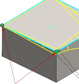
You can manipulate and assign radius values to the control points between the vertices of a symmetric or asymmetric variable size fillet.
Control Points
- You can assign a radius value to each control point, or assign values to one or both enclosing vertices.
-
The system defaults to three control points located at equidistant increments of 25%, 50%, and 75% along the edge between the two variable radii.
-
You can change the relative position of each control point using the following methods:
- Change the percentage of the control point in the callout
-
Select the control point and drag it to a new location
Adding and Subtracting Control Points
You can add or subtract control points along the edge you select to fillet, either as you create the fillet or after you create the fillet by using
Edit Feature. Adding or subtracting control points along the edge positions the control points in equidistant increments along that edge.
-
Add control points: You can select a control point and Ctrl-drag to create an additional control point at a new location. Or, from the PropertyManager, you can increment the value in Number of Instances
 . Adding new control points through the PropertyManager adds points in the default positions.
- Subtract control points: You can remove specific control points by right-clicking and selecting Delete from the shortcut menu. Or, from the PropertyManager, you can decrement the value in Number of Instances . Deleting new control points through the PropertyManager removes the points from the default positions.
Filleting Multiple Edges
You can select more than one edge to fillet. Complete each edge before selecting any additional edges under
Items to Fillet 
, in the following manner:
- Apply a radius to each vertex first
-
Apply radius values to one or all control points
-
Change the position of a control point before or after you apply a radius value
-
Add new control points, if necessary
For asymmetric fillets, multi-edge control points appear for vertices with more than one filleted edge.
To reverse which side of the fillet Distance 1  and Distance 2
  define, click a multi-edge control point. In the Reverse Orientation dialog box, select the edges you want to reverse orientation for.