The following items are required for a component to be used as a Tube Section in SOLIDWORKS Routing.
Names of routing sketches and dimensions are case sensitive.
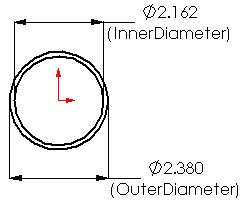
Pipe Sketch
- A front-oriented sketch named PipeSketch
- Two concentric circles, centered at the origin of the sketch, with dimensions named:
- InnerDiameter@PipeSketch
- OuterDiameter@PipeSketch
- The inner circle must be defined as For construction
To avoid errors in the sweep feature when creating tube routes, the tube thickness should be no greater than 0.25 times the outer diameter. (That is, make the outer diameter no more than twice the inner diameter.)
Example:

Sweep-path sketch
- In a 3D sketch, a line normal to the PipeSketch
- A concentric relation between the endpoint of the line and the centerpoint of the circles
Example:

Feature
A
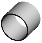
Sweep 
using:
- PipeSketch for Profile
- The 3Dsketch for Path
- The Thin Feature option to set the wall thickness
Example:

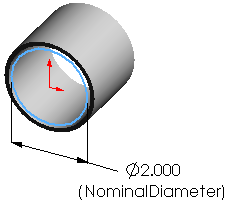
Filter Sketch
- A sketch named FilterSketch
- A circle with a dimension named NominalDiameter@FilterSketch
Example:
