The Cameras tab lets you create,
configure, manage, and use various cameras to view and record a scene.
Camera Tree
Each camera in the project is listed near the top of the Cameras
 tab in the Palette.
In the list at the
upper
left
of the tab, select the display option to use.
- To select a camera for editing, click its name or icon in the
Camera tree.
- To switch to a different camera in the project, double-click its
name or icon in the Camera tree, or drag the camera into the 3D Viewport.
Camera Parameters
The parameters are organized onto five subtabs: General, Transform, Stereo/360, Filters, and Advanced.
General
| Name |
Shows the name of the
camera. Type over the name to change
it.
|
| Locked |
Prevents you from changing any
parameter of the camera. |
| Keep Above
Floor |
Prevents you from moving the
camera below the floor in the project. When
cleared, you can move the camera anywhere. In addition, a
ring appears around the Top perspective selector in the
Camera panel.
Click the ring to switch the camera perspective to directly
under the scene, looking up.
|
| Aspect
Ratio |
Specifies
the aspect ratio of the rendered area within the 3D Viewport. Type over the default values or select from
preset categories and values to change them.
|
| Type |
Specifies
the camera type. Select one of the following:
- Orthographic
- Perspective
- 360
|
| Lens |
(Available when Type is set to Perspective.)
- Perspective. Controls the amount of
perspective distortion in the camera by changing the
focal length and position of the camera's virtual lens
toward
the viewing direction.
Smaller
perspective values reduce perspective distortion and
increase the focal length of the lens. Larger values
do the opposite.
- Focal
Length (mm). Controls the amount of
perspective distortion in the camera according to an
accurate simulation of optical physics in camera
lenses.
Although the 3D position
of the camera remains unchanged, smaller values
provide a wider angle of view and therefore seem to
move the camera further away. Larger values do the
opposite.
|
| Depth of
Field |
(Available when Type is set to Perspective.)Depth of field (DOF) is the rate that blur
increases for objects further from the focal plane. The
depth of field of a specific lens is the range of acceptable
focus in front of and behind the primary focus setting. It
is a function of the specific lens used and the distance
from the lens to the primary focal plane, and of the chosen
aperture. Larger apertures narrow the depth of field;
smaller apertures increase it.
- Enable
Depth of Field. Turns on depth of
field options.
- Focal
Distance.
Specifies
the distance between the camera and the point of
optimal focus.
To select the focal
point, click Pick and click a position in the
Viewport.
- Aperture (mm). Uses millimeters to
set the diameter of the opening in the virtual lens
of the selected camera.
In a real
camera, this is the size of the opening that light
passes through (usually given in terms of its f
stop) to reach the film. The larger the f stop,
the smaller the opening. 3D software packages
sometimes mimic the effects of different aperture
settings on a recorded image during the rendering
process.
- F
Stop. Uses the f stop value to
specify
the diameter of the opening in the virtual lens of
the camera.
|
Transform
| Distance/Dolly |
Determines the distance
between the camera and the look-at point. |
| Longitude |
Rotates the camera around the
look-at point. |
| Latitude |
Moves the camera
vertically. |
| Twist |
Tilts the camera left or
right without moving its 3D position. |
| Position
XYZ |
Indicates the current 3D
position of the camera relative to the scene's world
origin. |
| Camera
Positioning |
These parameters let you view
an overlay showing the distance between the world origin and the
cameras you select in the Cameras tab of the Palette. The distances are
accurate provided the model scale in the scene is accurate. To use these parameters, you must view the
scene from another camera.
- Show in
Viewport. Displays the distance of this
camera to the world origin in the Viewport.
- Height from
Floor. Lets you move the camera height
above the floor in the scene
- Floor
Distance. Lets you move the camera
horizontally closer to, or further from, the world
origin of the scene.
- Focal
Height. Lets you
specify
the height of the camera's focal plane, relative to the
floor in the scene.
|
| Follow |
(SOLIDWORKS Visualize
Professional) The Follow
parameters let you specify a model or another camera for this
camera to Follow and
Aim at. |
Stereo / 360
(SOLIDWORKS Visualize Professional)
This subtab is available when, on the General subtab, Type is set
to Perspective or 360. The subtab name and available options vary
depending on which Type is selected.
| Subtab Name |
Description |
Example Image |
| Stereo |
(Available when Type is set to Perspective.) Provides
Stereoscopy
options to support stereo rendering, which computes two
images at the same time, and merges them to produce a
three-dimensional appearance in a single image.
|
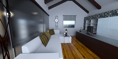 |
| 360 |
(Available when Type is set to 360.) In addition to the
Stereoscopy
options, provides options to support a nonlinear type of
projection that captures the whole 360° environment around
the camera’s position into a wide screen image that
resembles a photo with an extreme fish eye lens.
|
 |
360
| Preview 360
Panorama |
Shows a low-resolution preview of
the final 360 panorama. 360 is not available in the
Preview render mode.
|
| Set Startup
View |
Specifies
the active camera angle as the startup view for the 360
experience. |
Stereoscopy
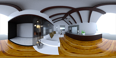
| Mode |
Select one of the following:
- Mono. Uses normal (monoscopic)
rendering using a single camera to produce a single
image.
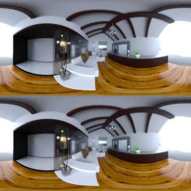
- Stereo
Two-Up. Uses stereoscopic rendering to
produce two images (one for each eye). Displays both
images simultaneously, with the left-eye image on top
and the right-eye image on the bottom.
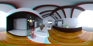
- Stereo
Anaglyph. Uses stereoscopic rendering to
produce two images (one for each eye). Merges the two
images using chromatically opposite color filters (red
and cyan).
|
| Eye Separation
(m) |
(Not available for Mono mode.) Specifies the
distance between the left eye and the right eye. Type a value or
move the slider. |
| Focal
Distance |
(Not available for Mono mode or 360 type.) Distance between the
camera and the focal point. Defines the zero parallax or point
of convergence between the left and right images for a given
Eye Separation. Type
a value, move the slider, or click Pick and select an object in the 3D
viewport. |
Filters
| Post-Processing
Options |
(SOLIDWORKS Visualize
Professional) Post-processing is the manipulation of a rendered
image, either to improve the image quality, or to create effects
that cannot easily be achieved within the 3D software. You can
set some 3D software packages to automatically apply
post-processing effects, such as motion blur or depth of field,
after a frame is rendered. These options add
photographic effects to the scene when viewed through this
camera. All imagery produced from this camera – including
the realtime view in the Viewport, and snapshots and all
types of rendering and animations – uses these settings.
- Enable
Post-Processing. Activates
post-processing of this camera view and all imagery that
comes from it.
- Apply To
Geometry Only. Post-processing effects
only applied to the model, and not a backplate or
background color.
- Color
Filter. Applies the selected color as a
filter on the lens of the virtual camera.
- Vignette. Creates a soft shadow near
the edges of the camera's field of view.
The vignette effect strengthens
with cameras that have more perspective (in contrast
to an orthogonal camera).
- Darken. Darkens the overall scene.
- Lighten. Lightens the overall scene.
- Saturation. Increases or decreases the
color saturation of the image
- Exposure. Increases or decreases the
density (brightness) of the scene.
- Gamma
Correction.
Specifies
the gamma of your monitor.
Available even when Enable Post-Processing is
cleared.
- Brightness. Makes the overall scene
brighter, which adds detail to shadows.
Available even when Enable
Post-Processing is cleared.
|
| Bloom |
(SOLIDWORKS Visualize
Professional) When you are in Fast or Accurate render modes, the
Bloom options
let you use and configure a bloom filter.
A bloom filter produces a fake feathering
effect that the human eye and camera lens create when light
hits specific angles on an object. It is an interpretation
of the world rather than a true physical and calculable
light. Because HDR image environment mapping creates
environments based on calculations, adding a bloom effect
gives an Iray-rendered scene the illusion of
realism.
The effect is only seen
on emissive materials.
- Enable
Bloom. Turns on a bloom filter.
- Intensity. Controls the bloom effect
brightness.
- Radius. Controls the radius of pixels
the bloom covers.
By increasing the
radius, you can make the bloom effect more
blurred.
- Threshold. Controls how much energy
hits a specific portion of an object.
The lower the number, the brighter the
bloom.
|
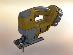
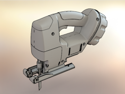
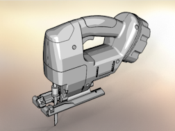
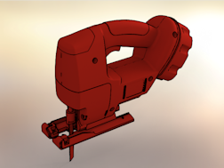
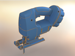
Toon
| Enable Toon |
Enables Toon options for the
current camera. Examples below show various Toon
options applied to this model of a jig saw: 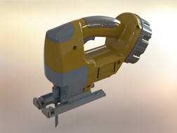 Original model, without Toon options |
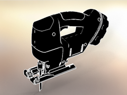
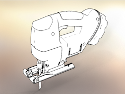
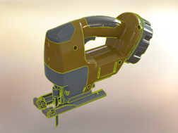
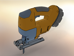
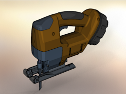
| Toon
Presets |
Provides a list of predefined
toon profiles that you can select.
|
Black Edges
|
|
|
White on Black
|
|
|
Black on White
|
|
|
Ambient Occlusion
|
|
|
Custom
|
|
|
| Edge
Color |
Changes the color of the
outlines. |
| Shading
Style |
Select a style:
|
Normal
|
Normal
shading, Edge
Color: yellow
|
|
Toon Shaded
|
|
Toon Detail
|
Toon
Detail: 0
|
|
|
Toon
Detail: 6.0
|
|
Color Override
|
Toon
Detail: 6.0, Color Override: white
|
|
|
Plain Shaded
|
Edge
Color: black, Color: red
|
|
|
Edge
Color: orange, Color: blue
|
|
Advanced
| Render
Region |
(SOLIDWORKS Visualize
Professional) Lets you render a region within the camera when
you do renderings with that camera. Select
Enable Region
for the current camera, and crop the Viewport to the region
constraining renderings by doing one of the following:
- Drag the white dots that appear to
specify
a region for cropped rendering.
- Enter the pixel dimensions in the
Palette.
|
| Motion
Blur |
(SOLIDWORKS Visualize
Professional) Motion blur is an artifact of real world
cinematography in which the camera's target object moves too
quickly for the camera to record accurately and therefore
appears blurred. Many 3D software packages simulate motion blur
as a rendering effect to increase the realism of 3D images or
animation. Motion blur is available only
for raytracing (either realtime or offline) in Accurate mode. In addition,
motion blur requires an animation that defines the
motion.
- Enable
Motion Blur. Activates motion blur for
the camera. The motion blur is the sum of motion from an
animated camera and geometry.
- Shutter
Time (ms).
Specifies
the quantity of motion blur.
|
| Rule of Thirds
Overlay |
This feature uses an overlay
of a thirds ruler or fourths ruler to aid with composition when
using the camera.
- Enable Grid
Overlay. Turns the grid overlay on and
off.
- Overlay
Type. Lets you
specify
the grid overlay to thirds or fourths.
- Grid Line
Color.
Specifies
the grid color.
|
Camera Selection
| Reset
Camera |
Resets the camera to the default
settings. |
| Save
Camera File |
Saves the camera to the Cameras
library using the SOLIDWORKS Visualize camera file format. You can then
load the camera in a separate project or share the camera with other
SOLIDWORKS Visualize
users. |
| New
Camera |
Creates a new camera
preset. |
| Load
Camera |
Opens the Open Camera dialog box to the
Cameras library so that you can load an existing saved
camera. |