DimXpert Size Dimension
Use the DimXpert Size Dimension
tool  to place tolerance size dimensions on DimXpert features. In the following
procedure you dimension a simple hole.
To use the DimXpert Size Dimension tool:
Click Size Dimension
 (DimXpert toolbar) or Tools,
DimXpert, Size
Dimension.
Select the face of the feature to dimension.

 To define a width feature,
you can also select a linear edge bounded by two parallel planes that
are perpendicular to the edge. Edge selection is only supported for width
features.
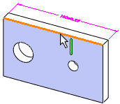
The Feature
Selector appears in the graphics area with a default feature
type selected. If necessary, select a different type of feature in the
feature selector.
 Use the appropriate feature
selector option when defining a new width or compound hole from multiple
faces.
Click to place the dimension. 
The DimXpert
PropertyManager appears. The selected feature is listed as
Tolerance Feature  under Reference Features.
 In general, you can attach
dimensions to any edge of the feature or to any pattern instance. Select
the dimension and use its drag handle to reposition the dimension.
Set the PropertyManager options and click  .
.
The DimXpertManager updates to include the
feature and dimension type.
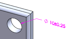
Notes
Default Tolerance values. Set
the tolerance values in Tools,
Options, Document
Properties, DimXpert, Size
Dimension.
Pattern features. DimXpert recognizes
many patterns and defines instance counts automatically. The format is
defined in the DimXpert callout format file. If DimXpert does not automatically
recognize pattern features, you can define them using the DimXpert Pattern Feature
tool.
Callout format file. Some dimensions
are displayed using a callout format. A template file (txcalloutformat.txt)
that defines this format is found under Tools,
Options, System
Options, File Locations,
DimXpert Callout Format File.
The template lets you define individual formats for each dimensioning
standard.
Grouping. When the selected
feature is defined as a datum or is controlled by a geometric tolerance,
the size dimension, datum feature symbol, and geometric tolerance are
automatically combined into an annotation group.
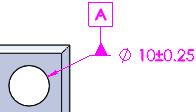
Depth Dimensions. Depth dimensions
are applied to blind features only. Other criteria, such as the geometry
bounding the top of the feature and the geometry of the blind end condition,
can affect whether a depth dimension is created.
Threaded holes. When a hole
is threaded, the thread designation is used instead of the hole diameter
and tolerance. This is true for hole types defined with the Hole Wizard
or linked to a cosmetic thread.
Supported Features
|
Feature |
Example and Dimension Type |
Notes |
|
|
|
|
|
Boss |
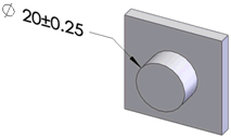
Diameter |
|
|
|
|
|
|
Chamfer |
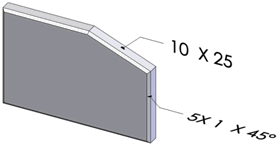
Angle-distance Distance-distance |
DimXpert dimensions SolidWorks chamfers with the method used to define
them.
Chamfers recognized by their topology are dimensioned Distance-Distance. |
|
|
|
|
|
Cone |
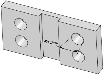
|
A set of external or internal cones must have the same included angle
and lie on a common plane. |
|
|
|
|
|
Cylinder |
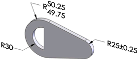
Radius |
|
|
|
|
|
|
Feature |
Example
and Dimension Type |
Notes |
|
Fillet |

Radius |
|
|
|
|
|
|
Intersect Circle |
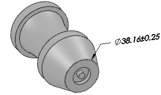
|
A circle derived at the intersection of a cone and plane. The cone must
be perpendicular to the plane, and it cannot be created from an ellipse.
The cone and plane can be interrupted by a fillet or chamfer. |
|
|
|
|
|
Counterbore Hole |

|
|
|
|
|
|
Countersink Hole |

|
|
|
|
|
|
Feature |
Example
and Dimension Type |
Notes |
|
Simple Hole |
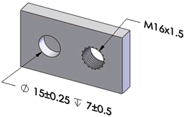
Diameter and depth (when blind), or thread designation and depth (when
blind) |
|
|
|
|
|
|
Notch |
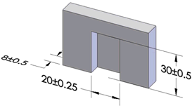
Length, width, and depth (when blind) |
|
|
|
|
|
|
Slot |
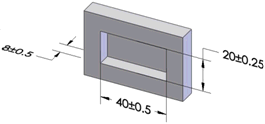
Length, width, and depth (when blind) |
Specify the dimension type in the DimXpert options dialog
box. |
|
|
|
|
|
Width |
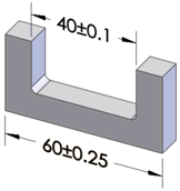
Width |
|
|
|
|
|
|
Feature |
Example and Dimension Type |
Notes |
|
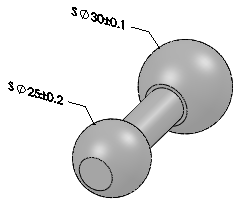
Sphere |
|
|