Introduction
Structural beams can be simplified for the sake of performance in Simulation
to be modeled with beam elements. The size of the problem and the resources
required are reduced dramatically in this case. For the beam formulation
to produce acceptable results, the length of the beam should be 10 times
larger than the largest dimension of its cross section.
Each straight structural member is defined by a straight line connecting
two joints at its ends. A curved structural member is modeled with a number
of straight beams. The cross section of a beam is assumed to be constant
throughout its length. Internally, the programs meshes each beam by creating
a number of beam elements. Each beam element is defined by two end nodes
and a cross-section. When viewing the mesh and results, beam elements
are represented by cylinders regardless of the actual cross section.
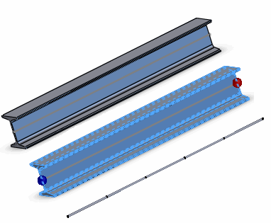
The figure illustrates how a structural member is modeled. The top image
shows the structural member. The middle image shows the joints when the
structural member is defined as a beam. The lower image shows the mesh,
where the beam is subdivided into a number of beam elements represented
by cylinders. 
 Click here
to see how a curved structural member is modeled as a beam.
Beam elements are supported for Static, Frequency, Buckling and Nonlinear
studies. Large displacement solution
in Static studies is not supported for beams.
Creating Beams
Structural members that are created as Weldment
features mesh with beam elements by default. You have the option to treat
these structural members as solids by selecting their icons in the Simulation
study tree and select Treat as Solid.
For short structural members (ratio of length over largest orthogonal
cross-sectional distance from the centroid is less than 3.0), it is recommended
to use a solid mesh.
To treat extruded, mirrored, or imported bodies that have a constant
cross-sectional profile across their length as beams, select their icons
in the Simulation study tree and select Treat
as Beam.
 The option Treat
as Beam is not available, when the ratio of a body's length over
the largest orthogonal cross-sectional distance from its centroid is smaller
than 3.0. This limitation applies only to structural members created with
features such as Extrude, Revolve, Sweep,
etc.
You can define a structural member as a truss or beam in the Apply/Edit Beam
PropertyManager.
Related Topics
Beams
Trusses
Performing
Analysis Using Beams or Trusses
Apply/Edit
Beam PropertyManager
Beam
Directions
Edit
Joints PropertyManager