Connector - Spring
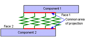
A Spring  connects
parallel planar faces or concentric cylindrical faces with springs that
can resist tension only (cables), compression only, or tension and compression.
Note: Spring
connectors for surfaces and sheet metal bodies are available for static,
frequency, and buckling studies. The feature is not available for composite
shells. For nonlinear studies, define connectors between two vertices
only.
Type
Compression Extension
 . Resists tension and compression. Available for static,
frequency, buckling, and nonlinear studies.
Compression only
 . Resists compression only. Available for static and nonlinear
studies.
Extension only
 . Resists tension only. Available for static and nonlinear
studies.
Flat parallel
faces.
NOTE:
Edges of shells refer to edges of surface bodies and the face containing
the smallest dimension for sheet metal bodies. The program meshes the
sheet metal bodies with shell elements and converts the face of the sheet
metal containing the sheet metal thickness into an edge.
Options
 Not all options are available for all types
of springs.
Units
 .
.
Distributed.
The value of the stiffness per unit area (or unit length if you selected
an edge of shell). The equivalent total stiffness equals the common area
(or common length if you selected an edge of shell) of projection multiplied
by the distributed stiffness.
Total.
The value of the total stiffness. The total stiffness is distributed uniformly
on all selected faces or edges of shells.
Normal Stiffness
or Radial Stiffness
 . Stiffness normal to the faces or the edges of shells.
Tangential Stiffness
or Shear Stiffness  . Stiffness in the plane of the faces or tangential to edges
of shells.
Rotational Stiffness
 . Torsional stiffness between two points.
Compression preload
force. Not available for Extension-only
spring.
Tension preload
force. Not available for Compression-only
spring.
Symbol Settings
Edit
color. Select a color for the symbols.
Symbol Size  . Set the size of the symbols.
Show preview.
Toggles the display of the connector symbols in the graphics area.
Tips
NOTE:
If you selected an edge of a shell from a body and face of a solid or
edge of a shell from another body, springs are introduced along the common
length of projection of the edges from one body to edges or faces of another
body.

You can split one or both faces by projecting
one face onto the other. Define a spring between the new, aligned faces.
When viewing results, plot the deformed shape
with 1.0 scale factor to ensure there is no interference between components.
When interference occurs, the results are not valid. Define contact conditions
between the interfering faces before re-running the study.
Related Topics
Connectors
PropertyManager
Summary
of Connectors