Remote Displacement (Rigid Connection)
You can use this option when the replaced components are adequately
rigid with respect to the modeled components and you know the remote translations
and/or rotations that can replace its effect on the rest of the model.
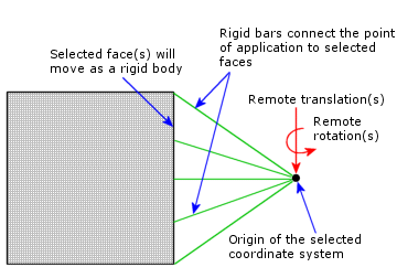
The point of application of the constraint is effectively connected to
the selected faces by rigid bars.
The selected face(s),
being rigidly connected to a common point, can only deform as a rigid
body. The area and shape of each face remain unchanged. High stresses
can develop near faces with rigid connections.

To apply a remote displacement (Rigid connection) to
a face:
In the Simulation study tree, right-click the
External Loads  icon
an select Remote Load/Mass
  .
.
Under Type,
select Displacement (Rigid connection).
In the graphics area, click the faces to which
you want to apply the remote displacement.
Under Reference
Coordinate System, select Global
(default global coordinate system), or User
defined.
Under Location,
do the following:
Under Translation,
do the following:
Set Unit
 to the desired unit of length.
Click the translation components that you
want to specify and type in their values.
Under Rotation,
do the following:
Set Unit
 to the desired unit of rotation.
Click the rotation components that you want
to specify and type in their values.
Click  .
.