Cross Sections 
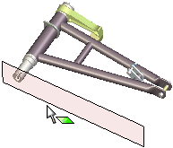
Create cross section planes:
Use the default XY
cross section plane.
Select a plane from the Cross
Section tab.
Select
a face in the graphics area, then select Face
Plane on the Cross Section
tab.
Double-click a point on a face to create a cross
section plane parallel to the face.
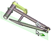
You can drag the plane to change the cross section. The edges of the
model that touch the cross section plane are shown in red.
To create and manipulate a cross section:
-
Click Insert Cross Section
 or Tools, Cross Section.
A cross section plane appears, normal to the model.

Drag the plane, which moves along the axis normal
to the model.

On the Cross
Section tab  , select from the following options.
 XY Plane
 YZ Plane
 XZ Plane
 Face Plane. First select a face, then select this
option to create a plane parallel to the selected face. Double-clicking
a face also enables this option.
 Flip. Flips the model along the currently displayed
plane to display the other side of the model.
 View normal to Plane. Displays the model normal to
the plane.
 Show Plane. Shows the cross section plane.
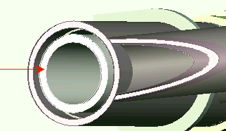
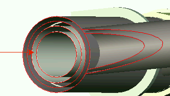
 Show Cap. Displays the edges as capped solid faces.
|

Cross section capped and solid |

Cross section uncapped and hollow |
To release the Insert Cross Section  tool, click it again.