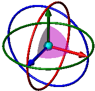
Move/Copy Bodies
In multibody parts, you can move,
rotate, and copy solid and surface bodies, or place them using mates.
To move, copy, rotate, or mate a solid or surface body:
Click Move/Copy Bodies  (Features
toolbar) or Insert, Features,
Move/Copy.
The Move/Copy Body PropertyManager
appears. This property manager displays one of two pages:
Click Translate/Rotate
or Constraints at the bottom of
the PropertyManager (if necessary) to switch to the page you want.
Set options
in the PropertyManager as described below.
Translate/Rotate
Bodies to Move/Copy
Solid and
Surface or Graphics Body to Move/Copy  . Select the
bodies in the graphics area to move, copy, or rotate. The selected bodies
move as a single entity. The bodies that are not selected are treated
as fixed. A triad
appears at the center of mass of the selected bodies.
Copy.
Select to copy bodies, and set a value for Number
of Copies  . Clear to move the bodies instead of
copying them.
Translate
Do one of the following:
Set
the Delta X  ,
Delta Y
  , and
Delta Z
  values
to reposition the bodies.
Drag
the triad's arrows in the graphics area to reposition the bodies.
The Delta X  , Delta
Y
  , and Delta Z
 values dynamically update.
Select
an edge in the graphics area to define the translation direction.
Set
a value for Distance  . Type a negative number to switch the translation direction.
- or -
Select
a vertex in the graphics area.
If
necessary, click To Vertex  to select a second vertex.
The bodies
move the direction and distance defined by the vertices.
A preview of the moved bodies appears.
Click  .
.
Rotate
Set values
for the coordinates of the rotation origin (the point that the bodies
rotate about). The default values are the coordinates of the center of
mass of the selected bodies.
X Rotation Origin 
Y Rotation Origin  .
.
Z Rotation Origin  .
.
The triad moves in the graphics area to the
new location of the rotation origin.
Do one of the following:
- or -
Select
a vertex in the graphics area.
Set
values for X Rotation Angle  , Y Rotation Angle
 , and Z Rotation Angle
 .
.
A preview
of the rotated bodies appears.
Click  .
.
Constraints
Bodies to Move
Solid and
Surface or Graphics Body to Move/Copy  . Select bodies
in the graphics area to move when the mate is applied. The selected bodies
move as a single entity. The bodies that are not selected are treated
as fixed.
Mate Settings
Entities
to mate  . Select two entities (faces, edges, planes,
etc.) to mate together.
Add.
Click to add the mate after selecting a mate type and setting parameters
below. Click Undo to clear selections.
Select a mate type. All the mate types are
always shown in the PropertyManager, but only the mates that are applicable
to the current selections are available.
 Coincident
 Parallel
 Perpendicular
 Tangent
 Concentric
 Distance.
Select, then set Distance. Select
Flip Dimension to change the direction.
 Angle.
Select, then set Angle.
Mate Alignment.
Aligned
 . Places the bodies so the normal or axis vectors for
the selected faces point in the same direction.
Anti-Aligned
 . Places the bodies so the normal or axis vectors for
the selected faces point in opposite directions.
Mates
The Mates box contains all the
mates in the mate set (all the mates added while the PropertyManager is
open). When there are multiple mates in the Mates
box, you can select one to edit that mate.
 In multibody parts, you can apply multiple
sets of mates to the same body. Mates specified within different sets
can conflict with each other. For example, you can apply a perpendicular
mate between two faces in one set, and in a different set, apply a parallel
mate between the same two faces.
Options
Show preview.
When selected, a preview of a mate occurs when you make enough selections
for a valid mate.