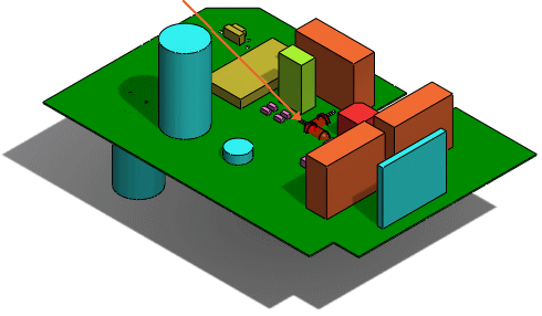
You can add a SolidWorks® user-defined coordinate system to a component that is not modeled with the SolidWorks origin. You might obtain such components from a manufacturer website or from other CAD systems.
CircuitWorks™ assigns the user-defined coordinate system as the ECAD origin when you export the assembly into CircuitWorks.
If you insert components without a user-defined coordinate system into a CircuitWorks assembly, CircuitWorks assigns SolidWorks origin as the ECAD origin.
To add your own coordinates to a component, see SolidWorks Help: Coordinate System.
When you name the user-defined coordinate system CWX before inserting the component in the CircuitWorks Library, CircuitWorks assigns the user-defined coordinate system as the ECAD origin and correctly positions the components when you insert them into a circuit board assembly.
CircuitWorks interprets the positive Z-direction of a user-defined coordinate system as perpendicular to a circuit board assembly. The XY plane represents the board surface, and the X- and Y- directions control the angle at which the component is inserted into the assembly.
To assign a name other than CWX to the user-defined coordinate system representing the ECAD origin, click , select
SolidWorks Export, and modify the
Import and export components relative to this coordinate system option.
Example: LED Orientation With and Without Coordinates Defined
| The coordinates of an externally manufactured LED set the Z-direction parallel to the base of the LED. |

|
| You add the LED to the CircuitWorks Library without defining a coordinate system named CWX. When you insert the LED components into the board assembly after building it in CircuitWorks, the LEDs are horizontal. |

|
| Before adding the component to the CircuitWorks Library, add a coordinate system named CWX to the LED component in SolidWorks. |

|
| The LEDs are properly oriented when you insert them into the board assembly. |
 |