Vary Sketch
Select the Vary
Sketch option to let the pattern instances change dimensions as
they repeat.
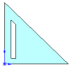
In this example, the seed (cut-extrude)
feature is patterned three times to the right. You maintain some of the
dimensions of the seed feature in the pattern instances, while allowing
the height of the pattern instances to vary.
|

|

|

|
|
Seed feature |
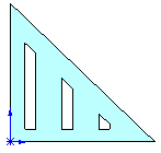
Vary
Sketch selected.
The instances maintain the relation
to the sloping edge, the width, and the dimension to the bottom edge,
based on the dimensions and relations of the seed feature. The height
varies because you did not dimension that in the seed feature. |
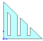
Vary
Sketch cleared.
The instances remain the same,
regardless of the defining geometry. |
To create a variable pattern:
Create
the base part. This example uses an extruded triangle on which you sketch
and pattern a cut-extrude feature.
Create
a sketch for the seed feature on the base part. In this example, sketch
a polygon to create a cut-extrude feature. Observe the following recommendations:
The feature
sketch must be constrained to the boundary that defines the variation
of the pattern instances. For example, in the illustrated pattern, the
angled top edge of the seed feature is parallel and dimensioned to the
angled edge on the base part.
The feature
sketch should be fully defined.
Dimension
the measurements that remain unchanged in the sketch, and make sure to
not
dimension the measurements that vary in the pattern instances.

In this example,
make sure to set these relations and dimensions because they remain unchanged
in the pattern instances:
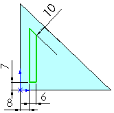
Set
the top sketch line parallel to the sloping edge of the part and dimension
(10 mm).
Dimension
the bottom sketch line to the bottom edge of the part (7
mm).
Dimension
the width of the sketch (6 mm).
 Do not
dimension the height of the sketch because you want it to vary in the
pattern instances.
Dimension
the lower-left vertex of the sketch to the left vertical edge of the part
(8 mm). Use this dimension later
for the pattern direction.
Click Extruded Cut  on the Features
toolbar, or click Insert, Cut,
Extrude, and create the seed feature.
In the
FeatureManager design tree, select the cut-extrude feature.
Click Linear Pattern  on the
Features toolbar, or click Insert, Pattern/Mirror,
Linear Pattern.
In the
PropertyManager, under Direction 1:
Select
the driving dimension (8 mm) for
Pattern Direction. If necessary,
click Reverse Direction  to pattern the instances to the right.
Set
the values for Spacing  and Number of Instances
 .
.
Note the preview
shows three instances that match the seed feature.
Under Options, select Vary
Sketch.
The preview
disappears.
Click OK  .
.
The height
of the pattern instances vary while other relations are maintained.
