Auxiliary View
An Auxiliary View is similar to a Projected View,
but it is unfolded normal to a reference edge in an existing view.
You can create an auxiliary view of an exploded assembly view.
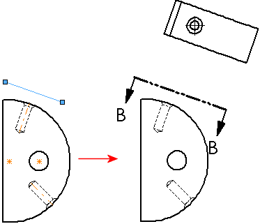
You can use sketched lines for
folding. In this example, to properly orient the auxiliary view, add a
perpendicular relation between the sketched line and the temporary hole
axis.

To create an auxiliary view:
-
Click Auxiliary View  on the Drawing toolbar, or click Insert,
Drawing View, Auxiliary.
The Auxiliary
View PropertyManager appears.
-
Select a reference edge (not a horizontal or vertical edge, which
would create a standard Projection View).
The reference edge can be an edge of a part, a silhouette edge,
an axis, or a sketched line.
 Auxiliary views are not available from
detail views.
As you move the pointer, a preview of the view is displayed if you
selected Show
contents while dragging drawing view. You can also control
the alignment
and orientation
of the view.
Move the pointer until the view is where you want,
then click to place the view. You can edit
the view labels and change
the alignment of the view if necessary.
If you used a sketched line to
create an Auxiliary View, the sketch is absorbed so you cannot delete
it inadvertently. You can delete sketch entities while editing the sketch.
To edit a sketched line used to create an auxiliary
view:
Select the Auxiliary View.
In the Auxiliary
View PropertyManager, select Arrow.
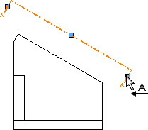
Right-click the view arrow and select Edit
Sketch.
Edit the sketched line, then exit the sketch.
To edit the view arrow:
|
On the view
arrow, drag the:
Center
handle to move it End handle
to resize it |

|