Virtual Clips
You can create virtual clips to position a route during the initial
stages of a design. A virtual clip is a part with:
One or two Route
Points. With one Route Point, the route is constrained to pass
through that point with no consideration of direction. With two Route
Points, the route passes in a straight line between the two points, so
direction is constrained.
An axis to represent
the path the route takes through the virtual clip. The axis defines
the route centerline for clips that you have pre-placed in the assembly,
so you can select them while using Auto
Route. If you name this axis Clip
Axis, you can use it to align the virtual clip with an edge or
axis in the assembly.
A mate reference
to place the part when you add it to an assembly. (optional) Add
solid geometry such as an extrude feature to provide faces and edges to
define mate references. Then hide the solid so it will not be not visible
when you insert the virtual clip in a route assembly.
Axis of Rotation.
(optional) Add to facilitate rotating the clip to the desired orientation.
Multiple configurations.
(optional) You can create multiple configurations of a virtual clip to
define different offset distances, then manually select the configuration
you want while placing the clip. If you want the virtual clip to automatically
resize when the cable diameter changes, you can add filter data and overlapping
configurations as you do for regular cable clips.
The virtual clip does not require any solid geometry. You can exclude
the virtual clip from the Bill of Materials.
To exclude virtual clips from the Bill of Materials:
Click File,
Properties.
On the Custom
tab:
For Property
Name, add IgnoreInBOM.
For Type,
select Yes or no.
For Value
/ Text Expression, type Yes.
Click OK.
When you create a Bill of Materials, the virtual clip does not appear
on it.
Examples
Two examples of virtual clips (cableconstraint.sldprt
and virtualclipsingleconstraint.sldprt)
are located in the Design Library, in the <install_dir>\data\design
library\routing\electrical
folder.
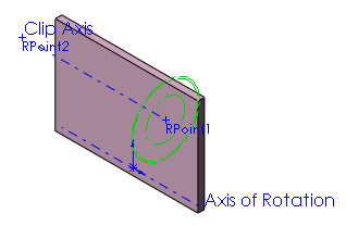
One configuration of cableconstraint.sldprt
is shown below. One of the edges of the extrude is used in a mate reference
definition, to facilitate positioning the part in an assembly. Axis
of Rotation and Clip Axis
can be used to rotate
or align the virtual clip. The virtual clip contains overlapping
configurations and filter data, so it automatically resizes to provide
different offset distances when the cable diameter changes.
