Reducer Parts
A reducer is used to change the diameter of the pipe or tube at a selected
location.
Requirements
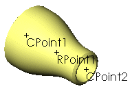
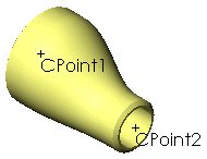
A reducer has two connection points (CPoints)
with different values for the Diameter
parameter.
You can also use the Routing
Component Wizard in the Routing Library Manager to prepare
a part for use in Routing.
You can create two types of reducers:
Concentric reducers
|
Concentric reducers must have a route point
(RPoint) between the CPoints.
The RPoint
enables you to insert a concentric reducer at a point in the middle
of a sketch segment. (Use Split Entities
 on the Sketch toolbar to insert a point in the middle
of a sketch segment.) on the Sketch toolbar to insert a point in the middle
of a sketch segment.)
When you add a concentric reducer to the
end
of a route segment, the route continues through the reducer and a short
route segment is added beyond the reducer so you can continue the route. |

|
Eccentric reducers
|
Eccentric reducers do not
have an RPoint.
You can insert eccentric reducers only at
the end
of a sketch segment, not at a point that you inserted in the middle of
a sketch segment. |

|
When you add an eccentric reducer to a route,
the route ends with the reducer. To continue the route from the other
end of the eccentric reducer:
- or -
To control the angular orientation of an
eccentric reducer in a route sub-assembly:
In the reducer part:
Create an axis that is perpendicular to
the route passing through the reducer.
Rename the axis Vertical.
In the route sketch in the route sub-assembly,
sketch a construction line that is perpendicular to the route and starts
at the point where you want to place the fitting.
When you insert the reducer into the route
sub-assembly, the Vertical axis
is aligned to the first construction line drawn in the route sketch at
the insertion point. If you have more than one construction line at the
insertion point, you are prompted to select one line for alignment.
 You can also rotate eccentric
reducers as you place them in an assembly by holding down Shift
and pressing the left and right arrow keys. Specify the rotation increments
in Routing
Options by setting Component
rotation increment (degrees).
Related Topics
Adding Fittings
General
Procedure for Pipes and Tubes