Configurations and In-context Components
You can have more than one instance of an in-context component that
is geometrically different in an assembly. To accomplish this, you must
have the following:
A driving part with more than one configuration.
A sub-assembly with more than one configuration.
A
driven part with more than one configuration. The driven part is built
in the context of the sub-assembly referencing the different geometry
in the two configurations of the driving part.
 When you create components
in the context of an assembly, the software saves them inside the assembly
file, and you can immediately begin modeling. Later, you can save the
components to external files or delete them. See Virtual
Components Overview.
This example
shows how to place geometrically different instances of the same component
into an assembly.
Create a cylindrical
part named tube.
Create two configurations
of tube named large
and small, each with a different
diameter for the cylinder. (For information on creating configurations,
see Creating
a Configuration Manually.)
Create
an assembly named pipes, and insert
tube into pipes.
Create
two configurations of the assembly pipes,
named large and small.
Specify the large configuration
of tube for the large
configuration of pipes, and the
small configuration of tube
for the small configuration of
pipes. (For information on specifying
component configurations, see Component Configurations in
an Assembly.)
Click
New Part  (Assembly
toolbar) or Insert, Component,
New Part, and create a part named
plug in the context of the assembly.
 To rename the in-context
component, right-click it and select Rename
Part.
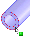
Select
the face on the end of tube for
the sketch plane. |

|
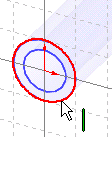
Select
the outer edge of the face, then click Convert
Entities  on the Sketch toolbar, or click Tools, Sketch
Tools, Convert Entities. on the Sketch toolbar, or click Tools, Sketch
Tools, Convert Entities.
A circle that references the outside diameter of tube
is added to the sketch. |

|
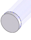
Exit the
sketch, then extrude a boss from the sketch. |

|
Click Edit Component  (Assembly
toolbar) to return to editing the assembly. (Assembly
toolbar) to return to editing the assembly. |
|
Open
plug in a separate window.
Create
two configurations of plug, named
large and small.
Return
to the pipes document window,
and activate the small configuration
of pipes.
In
the FeatureManager design tree, right-click the component plug
and select Component Properties.
In
the dialog box, under Referenced configuration,
select small. Make sure Change properties in is set to This Configuration, then click OK.
The diameter of the small configuration
of plug (the driven part) is now
defined by reference to the diameter of the small
configuration of tube (the driving
part).
Activate
the large configuration of pipes, and repeat steps 9 and 10 with
the large configuration of plug.
 Assigning the same names to the configurations in the driving
part, the driven part, and the sub-assembly is not required, but helps
you to keep them organized.
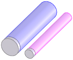
Create
another assembly, called plumbing,
and insert two instances of the sub-assembly pipes.
Set one instance of pipes to the
large configuration and the other
to the small configuration.
You now have two instances of the driven
part, plug, that are geometrically
different in the same assembly.

Related Topics
Component
Configurations in an Assembly
Creating
a Configuration Manually
Creating a Part
in an Assembly