Isotropic and Orthotropic Materials
Isotropic Materials
A material is isotropic if its mechanical and thermal properties are
the same in all directions. Isotropic materials can have a homogeneous
or non-homogeneous microscopic structures. For example, steel demonstrates
isotropic behavior, although its microscopic structure is non-homogeneous.
Orthotropic Materials
A material is orthotropic if its mechanical or thermal properties are
unique and independent in three mutually perpendicular directions. Examples
of orthotropic materials are wood, many crystals, and rolled metals.
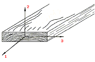
For example, the mechanical properties of wood at a point are described
in the longitudinal, radial, and tangential directions. The longitudinal
axis (1) is parallel to the grain (fiber) direction; the radial axis (2)
is normal to the growth rings; and the tangential axis (3) is tangent
to the growth rings.
Defining Orthotropic Properties For Solids
The orthotropic material directions throughout a component are defined
based on the reference geometry selected. If a part is manufactured such
that this is not true, then you should model it as different parts in
order to define orthotropic directions properly. For example, consider
the part shown in the figure:
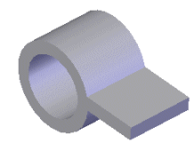
You need to model this part as two parts; the cylinder and the planar
sheet. You can then use a plane as the reference geometry for defining
the orthotropic material directions for the planar sheet and the axis
of the cylinder as the reference geometry for the cylinder.
|
|
|
|
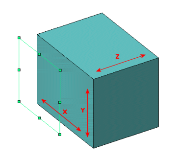
The X, Y, and Z directions for
an orthotropic material when a plane is used as a reference geometry. |
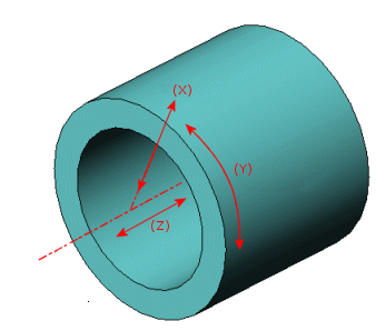
The radial (X), tangential (Y),
and axial directions (Z) for an orthotropic material when an axis is used
as a reference geometry. |
Defining Orthotropic Properties For Shells
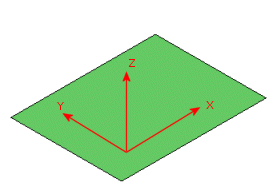
For a planar shell, select a plane that is parallel to the shell as
the reference geometry. The X and Y axes lie in the plane and the Z-axis
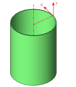
is normal to the plane. For a cylindrical shell, select the axis of the
cylinder as the reference geometry. The Y-axis is parallel to the axis
of the cylinder and the X-axis is tangential.
|
|
|
|
The X, Y, and Z directions of
an orthotropic material for a planar shell. |
The X and Y directions of an
orthotropic material for a cylindrical shell. |
 For composite shells, the X, Y and Z directions
for orthotropic material definition
are defined differently for each ply depending on ply
angle. Reference geometry is not considered for orthotropic material
definition.
In general, the software modifies the reference geometry as follows:
The software transforms the coordinate system
defined by the reference geometry such that the Z-axis becomes normal
to the plane of the shell. The plane of the shell is defined by the 3
corner nodes.
If the angle between the X-axis of the selected
reference geometry and the normal to the shell plane is larger than 45o, the program
projects the X-axis of the reference geometry on the shell plane to define
the modified X-axis.
If the angle between the X-axis of the selected
reference geometry and the normal to the shell plane is less than 45o, the program
projects the Y-axis of the reference geometry on the shell plane to define
the modified X-axis.
The Y-axis of the modified reference geometry
is then defined to complete a right-hand Cartesian coordinate system.
To define orthotropic
material: