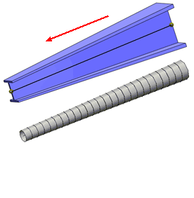
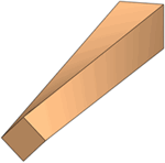
You can now treat tapered geometries as beams with varying cross-sectional sizes along their length. Tapered geometries should have the same cross-sectional profile along their length to be treated as beams.
In the Simulation study tree, right-click a solid body and select Treat as Beam. A tapered beam icon  appears in the study tree, if the solid body has a taper along its length.
The figure shows a tapered I-section beam with cross sectional size that decreases linearly along the direction shown. The tapered beam is represented by a straight line (neutral axis) connecting the two end joints. The lower image shows the mesh, where the beam is divided into a number of tapered beam elements represented by cylinders. Each element consists of two nodes having cross-sectional areas of the same shape but different sizes. The mesh and the results give you a visual indication of the taper along the beam length.

If a solid body does not qualify as a tapered beam, a warning recommends that you do not treat the body as a tapered beam. To qualify as a tapered beam, the solid body should maintain its cross-sectional profile along its axis, but with varying sizes.
This example shows a body with a twist along its length that does not strictly qualify as a tapered beam.
