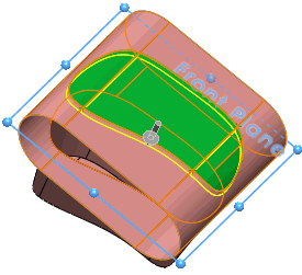
Viewing the Surface Extrude Options
Next, you examine the options used to specify the surface extrude for the model.
- Click Surface-Extrude2 and click Edit Feature
 .
.

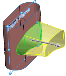
- To view one of the 3D faces used to create the surface extrude, select Face<1> under Faces to Extrude in the PropertyManager.
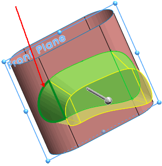
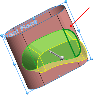
- To view the other faces used to create the surface extrude, select each of them under Faces to Extrude in the PropertyManager.
| A 3D face defines each end portion of the extude. |
|
| A planar face defines the middle portion of the extrude. |
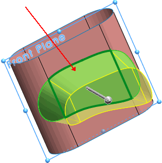
|
- To display the plane defining the direction of extrusion, click Front Plane in the PropertyManager.
Notice the extrude direction is normal to the front plane.
- Note the selected options:
- Cap end. Seals the Direction 1 end of the extrude with a translated copy of the selected 3D face.
- Delete original faces
 . Deletes the faces selected under Faces to Extrude
  . The 3D faces are removed from the model.
- Knit result
 . Knits the resulting extrude to the surface boundary where the original face is deleted.
- Close the PropertyManager.
To examine the other surface extrude created from 3D faces, rotate the model and repeat Steps 1 - 6 for
Surface-Extrude3.
