Extrude PropertyManager
Set the PropertyManager options based on the type of extrude feature.
From
Sets the starting condition for
the extrude feature.
Sketch
Plane. Starts the extrude from the plane on which the sketch is
located.
Surface/Face/Plane.
Starts the extrude from one of these entities. Select a valid entity for
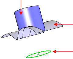
Surface/Face/Plane  . The entity can be planar or non-planar. Planar entities
do not have to be parallel to the sketch plane. The sketch must be fully
contained within the boundaries of the non-planar surface or face. The
sketch follows the shape of the non-planar entity at the starting surface
or face.
|
Extrude
feature |
Non-planar starting surface
Sketch entity |
|
|
Direction 1
End Condition. Determines how the feature extends. Set
the end condition type. If
necessary, click Reverse Direction
 to extend the feature in the opposite direction from
that shown in the preview.
Blind. Set the Depth
 .
.
Through All. Extends the feature from
the sketch plane through all existing geometry.
Up to Vertex. Select a vertex in the
graphics area for Vertex  .
.
Up to Surface. Select a face or plane
to extend to in the graphics area for Face/Plane
 . Double-click a surface to change the End
Condition to Up to Surface,
with the selected surface as the termination surface. If the sketch that
you extrude extends outside of the selected face or surface body, Up To Surface can do some automatic
extension of one analytic face to terminate the extrusion.
Offset From Surface. Select a face or
plane in the graphics area for Face/Plane
 , and enter the Offset
Distance
  . Select
to make the end of the extrusion a translation of the reference
surface, rather than a true offset. If necessary, select Reverse
offset to offset in the opposite direction.
Up To Body. Select the body to extrude
to in the graphics area for Solid/Surface
Body  . You can use Up
To Body when making extrusions in an assembly to extend the sketch
up to the selected body. Up To Body
is also useful with mold parts, if the body you extrude to has an uneven
surface.
Mid Plane. Set the Depth
 .
.
Direction of
Extrusion  . Select a direction vector in the graphics
area to extrude the sketch in a direction other than normal to sketch
profile.
Flip
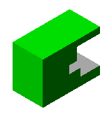
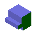
side to cut (Extruded cuts only). Removes all material from the
outside of the profile. By default, material is removed from the inside
of the profile.
|
|
|
|
Default cut |
Flip side cut |
Normal
cut (Sheet metal cut extrudes only).
Ensures that the cut is created normal to the sheet metal thickness for
folded sheet metal
parts.
Merge
result (Boss/Base extrudes only). Merges
resultant body into an existing body if possible. If not selected, the
feature creates a distinct solid body.
(Sheet metal parts only). Automatically
links the depth of an extruded boss to the thickness of the base feature.
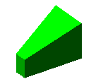
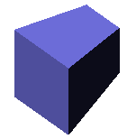
Draft
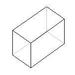
On/Off  . Adds draft to the extruded feature. Set
the Draft Angle. Select Draft outward if necessary.
|
|
|
|
|
No draft |
10° draft
angle inward |
10° draft
angle outward |
Direction 2
Set these options to extrude
in both directions from the sketch plane. The options are the same as
Direction 1.
Thin Feature
Use the Thin Feature options
to control the extrude thickness (not the Depth
 ). A Thin Feature base can be used as a basis for a sheet
metal part.
Type.
Sets the type of thin feature extrude.
One-Direction. Sets the extrude Thickness  in one direction
(outward) from the sketch.
Mid-Plane. Sets the extrude Thickness
 equally in both directions from the sketch.
Two-Direction. Allows you to set different
extrude thicknesses for Direction 1 Thickness
 and Direction 2 Thickness
 .
.
Auto-fillet
corners (Open sketches only). Creates a round at each edge where
lines meet at an angle.
Fillet
Radius  (Available if Auto-fillet
corners is selected). Sets the inside radius of the round.
Cap
ends. Covers (caps) the end of the thin feature extrude, creating
a hollow part. You must also specify the Cap
Thickness  . This options is available only for the
first extruded body in a model.
Selected Contours
Feature Scope
Specifies which bodies or components you want the feature to affect.