Connector - Bearing
A Bearing connector simulates
the interaction between a shaft and a housing through
a bearing. You have to model the geometries for the shaft and the housing.
You can define a bearing connector between split cylindrical faces of
a shaft, and cylindrical or spherical faces of a housing.
Type
Bearing

Selection (Cylindrical
Face )  . Select a full cylindrical face or concentric
cylindrical faces of smaller angles. This selection corresponds to the
shaft.
Selection (Cylindrical
or spherical face or circular edge on shell )  .
Select a cylindrical face, spherical face, or circular shell edge. This
selection corresponds to the housing.
Allow self-alignment
 . Define self-aligning
bearing connectors that allow an unrestricted off-axis shaft rotation.
You can define radial and axial direction stiffnesses for a self-aligning
bearing.

Stiffness
Units .
.
Rigid.
The selected face cannot translate or deform. The selection is free to
rotate about its axis.
Flexible.
Specify the stiffness:
Stabilize shaft
rotation. Select this option to prevent rotational instability
(caused by torsion) that can lead to numerical singularities.

Symbol Settings
Notes
Available for static, frequency, and buckling
studies.
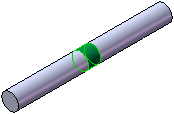
Use the Split
Line tool to define the cylindrical faces for the shaft. For example,
use the Split Line tool to create
the following highlighted face to apply a nearing connector.

Self-Aligning
Bearings. The program internally defines a resistance along the
circumferential direction of the cylindrical face. Self-aligning bearing
connectors allow an unrestricted off-axis shaft rotation.
When to use a
Bearing Connector. A bearing fixture assumes that the components
supporting the shaft are much more rigid than the shaft and can be considered
ground. When this assumption is not valid and the flexibility of the supporting
parts must be included, you should use a bearing connector formulation
to simulate the connection. You need to model not only the shaft but also
the housing.

Related Topics
Connectors
PropertyManager
Summary
of Connectors