Shrink Fitting
Shrink fitting is encountered in many engineering designs. It refers
to fitting an object into a slightly smaller cavity. Due to normal forces
that develop at the interface, the inner object shrinks while the outer
object expands. The amount of shrinkage or expansion is determined by
the material properties as well as the geometry of the components.
NOTES:
For accurate results, the overlap should be large
enough to overcome approximations introduced by meshing. For example,
the interference of cylindrical or spherical faces should be larger than
0.1% of the larger diameter at the interface for accurate results. However,
for static studies, use the Large
displacement option for moderately large interference. Use
nonlinear studies for large interference problems.
The contacting faces need not be cylindrical.
Shrink fitting is applied as a local contact condition. You can define
a shrink fit contact condition using the Shrink
Fit option in the Contact
Set PropertyManager.
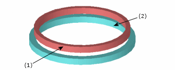
The following figure illustrates a shrink fit contact condition between
two rings. The outer diameter of the inner ring is slightly larger than
the inner diameter of the outer ring. The contact condition is defined
between the outer face of the inner ring (1) and the inner face of the
outer ring (2).

To apply shrink fit contact:
In the Simulation study tree, right-click Connections and select Contact
Set.
 Selecting Improve accuracy
for contacting surfaces with incompatible mesh (slower) for
static studies of assembly models with incompatible mesh is recommended.
In the PropertyManager, under Type,
select Shrink Fit.
In the graphics area, select the Set
1 contact entities. All entities should belong to the same component.
Selected entities appear in the Faces,
Edges, Vertices for Set 1 box  .
.
Select the Set
2 contact faces. All faces should belong to one component that
is different from the component used in step 3.
Selected faces appear in the Faces
for Set 2 box  .
.
Click  .
.
Mesh the model and run the study.
The above illustration is provided as a lesson
in the Online Tutorial.
Related Topics
Contact
Set
Multiple
Contact Conditions