Display Pane in Assemblies
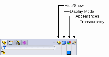
In the Display Pane, you can apply the following display settings for each component in an assembly:
 Hide/Show
 Display Mode
 Appearance
 Transparency
The display settings are stored in display states in the assembly.
You can:
-
Expand or collapse the Display Pane.
-
Click in the Display Pane to change display settings for each component.
-
View and override display settings for components of sub-assemblies.
-
Add new display states to the assembly, and change from one display state to another.
To expand or collapse the Display Pane:
-
Click  at the top of the FeatureManager pane (to the right of the tabs) to expand the Display Pane.
The Display Pane appears to the right of the FeatureManager pane. It has four columns:

-
Click  to collapse the Display Pane.
To change component display settings:
-
Move the pointer in the Display Pane until the component you want to change is highlighted in the FeatureManager design tree.
-
Do one of the following:
- or -
-
Click a selection.
Display settings include:
|
Display Setting
|
Icon
|
Description
|
Comments
|
|
 Hide/Show Hide/Show
|

|
Shown
|
|
|

|
Hidden
|
|
|
|
Show with Dependents
|
Shows all sub-assembly components, including those hidden in the sub-assembly, by creating a top-level override. Clear the override to return the sub-assembly components to the state defined in the sub-assembly.
|
|
 Display Mode Display Mode
|

|
Wireframe
|
|
|

|
Hidden Lines Visible
|
|
|

|
Hidden Lines Removed
|
|
|

|
Shaded With Edges
|
|
|

|
Shaded
|
|
|

|
Default Display
|
Components set to Default Display use the display mode of the top level assembly in the current window, as set on the View menu and toolbar.
|
|
 Appearance Appearance
|
(blank)
|
|
No appearance applied to the sub-assembly.
|
|

|
Part Color
|
Lower-right triangle shows the appearance of the part from the part document.
|
|

|
Override Color / Part Color
|
Upper-left triangle shows the override appearance specified in the assembly document.
|
|
 Transparency Transparency
|
(blank)
|
|
No transparency applied (part is opaque).
|
|

|
Transparent
|
75% transparency applied to the color of the component.
|
 Transparency
  and Appearance
  are linked. If you change the transparency slider under Optical Properties in the Color and Optics PropertyManager to a value other than 0.00, an override is applied in both the appearance and the transparency columns in the Display Pane. Likewise, if you apply transparency in the transparency column, an override also appears in the appearance column, because the transparency of the appearance has been changed to 75%.
For sub-assembly components, display settings are stored in the display state of the sub-assembly. Faded icons indicate display settings applied in the sub-assembly or part document. If you override a sub-assembly setting in the assembly, the icons change to normal color intensity (not faded).
|

|
Sub-assembly component display settings applied in the sub-assembly or part document.
|
|

|
Override applied in the assembly to change display mode of the sub-assembly component to Hidden Lines Visible.
|
 If you move the pointer over display settings in the Display Pane, a tooltip appears showing the name, configuration, and display state of the assembly where the setting is set.
You can remove display setting overrides from sub-assembly components.
To remove overrides from one sub-assembly component:
Click an icon in the Display Pane for the component and select Clear Override  .
.
All display setting overrides for that component are removed.
To remove all overrides for all sub-assembly components:
-
In the Display Pane:
- or -
-
Select Clear All Top Level Overrides  .
.
All display setting overrides for all sub-assembly components are removed.
 Display settings for top level components are stored in the display state of the top level assembly. Therefore, they always appear in the normal color intensity (not faded), and are not affected by the commands to clear overrides.
In the Display Pane, you can add new display states to the assembly, and change from one display state to another.
To create a new display state:
-
Right-click anywhere in the Display Pane and select Add Display State.
-
Type a name for the new display state and press Enter.
The name of the new display state appears in angle brackets after the configuration name at the top of the FeatureManager design tree.
To change from one display state to another:
Right-click anywhere in the Display Pane, select Activate Display State, and select a display state.