Mass Properties and Section Properties
|
Displays the mass properties of a part or assembly model, or the section properties of faces or sketches.
 You can assign values for mass and center of gravity to override the calculated values. This is useful when you create a simplified representation of a component, and want to assign the correct mass and center of gravity to the model. You can assign values for mass and center of gravity to override the calculated values. This is useful when you create a simplified representation of a component, and want to assign the correct mass and center of gravity to the model.
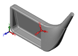
A tri-colored reference 3D triad displays at the origin. Another triad displays at the centroid of the part or assembly along with the mass properties and section properties.
|

|
Mass Properties
To display mass properties:
-
Select items (components or solid bodies) to be evaluated. If no component or solid body is selected, the mass properties for the entire assembly or multibody part are reported.
-
Click Mass Properties  (Tools toolbar) or Tools, Mass Properties.
 You can evaluate different entities without closing the Mass Properties dialog box. Clear the selections, then select the entity, and click Recalculate.
-
Set options as described below.
Results
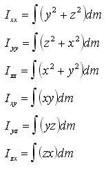
The results are displayed in the Mass Properties dialog box, and the principal axes and center of mass are displayed graphically on the model. The moments of inertia and products of inertia are calculated to agree with the following definitions:

The inertia tensor matrix is defined below from the moments of inertia:

Options
Output coordinate system. Select a coordinate system if you have defined one.
Selected items. Select items for which you want to calculate or assign mass properties. When you add, delete, or change items, click Recalculate to display new values.
Include hidden bodies/components. Select to include hidden bodies and components in the calculations.
Show output coordinate system in corner of window. Select to display the tri-colored reference 3D triad in the corner of the graphics area, or clear to show the triad at the origin.
Assigned mass properties. Select to assign values for mass and center of gravity to override the calculated values. Under Mass properties in the components's coordinate system, set values for the following:
-
Mass
-
Center of gravity (X, Y, Z)
-
Apply To. If the model has more than one configuration, select one of the following:
-
-
This configuration.
-
All configurations.
-
Specify configurations.
Options. Opens the
dialog box, to display the results using different units of measure.
Print. Prints the results directly from this dialog box.
Copy. Copies the results to the clipboard.
Close. Closes the dialog box.
 When you save the document, you can update the mass properties information. This enhances system performance, since the next time you access mass properties, the system does not need to recalculate the values (if the document is unchanged). To set this option, click Tools, Options, on the System Options tab, click
Performance
, and click the Update mass properties while saving document check box.
Section Properties
You can evaluate section properties for multiple faces and sketches that lie in parallel planes. You can evaluate different entities without closing the Section Properties dialog box. Clear the selections, then select the entity, and click Recalculate.
 When you evaluate more than one entity, the first selected face defines the plane for section property calculation.
To display section properties for multiple entities:
-
Select any of the following that lie in parallel planes:
-
one or more planar model faces
-
a face on a section plane
-
the crosshatch section face in a section view of a drawing
-
a sketch (click the sketch in the FeatureManager design tree or right-click the feature and select Edit Sketch)
-
Click Section Properties  (Tools toolbar) or Tools, Section Properties.
The results are displayed in the Section Properties dialog box.