Multibody Overview
|
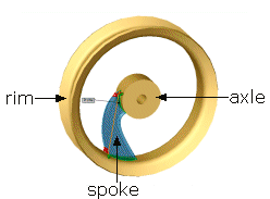
Part documents can contain multiple solid bodies. For example, when you design a spoked wheel, you know the requirements of the rim and the axle. However, you do not know how to design the spoke. With multibody parts, you can create the rim and axle, then create the spoke to connect the bodies.
|

|
You can manipulate multibody solids the same ways you manipulate single solid bodies. For example, you can add and modify features, and change the names and colors of each solid body.
A folder named Solid Bodies  appears in the FeatureManager design tree when there are solid bodies in a single part document. The number of solid bodies in the part document is displayed in parentheses next to the Solid Bodies folder
  . You can
organize and manage solid bodies
in the following ways:
-
Group bodies into folders in the Solid Bodies folder  .
.
-
Select commands to apply to all bodies within a folder.
-
List features that belong to each body.
You can create multiple solid bodies from a single feature with the following commands:
-
Extrude boss and cut (including thin features)
-
Revolve boss and cut (including thin features)
-
Sweep boss and cut (including thin features)
-
Surface cut
-
Boss and cut thicken
-
Cavity
Modeling techniques that you can use in a multibody environment include the following: