Measurement PropertyManager
The first step in creating a TolAnalyst study is to specify the measurement as a linear dimension between two DimXpert features.
Examples
|
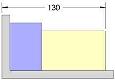
This measurement is the overall length of the three-part assembly.
|

|
|
|
|
|
This measurement is the gap between a hole and a shaft.
|

|
You can define measurements between any of the following DimXpert features. When the selected features are a combination of plane, line, or axis types, they must be parallel to one another. Surface types require that you use an exact point.
-
Point types: Sphere, Intersect Point
-
Axis types: Boss, Cone, Cylinder, Simple Hole, Counterbore Hole, Countersink Hole, Slot
-
Line types: Intersect Line
-
Plane types: Notch, Plane, Width
-
Surface types: Surface
To define a measurement:
-
Select faces of two features for Measure From and Measure To to establish the measurement.
 The selection of which feature is Measure From versus Measure To can affect the results.

A linear dimension appears in the graphics area.
-
Click to place the dimension.
The Message box turns from yellow to green, indicating the measurement is defined.
-
Select the PropertyManager options as necessary.
-
Click  .
.
PropertyManager Options
Measure From and Measure To
Selected face  . Select faces of two features to establish the measurement.
Specify Exact Point. Directs the measurement to a specific point on one or both features. This restricts the computation of the worst case results to be at the specified point instead of considering the entire boundary or axis of the feature.

The explicit point can be a vertex point or reference point (defined using Insert, Reference Geometry, Point). An explicit point is coincident with the plane or axis of the feature, but is not required to lie within the feature's boundary or axis endpoints.
These examples illustrate the use of explicit points using reference points.
|
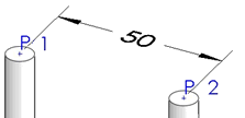
The measurement is defined using reference points created at the top of the two pins.
|

|
|
|
|
|
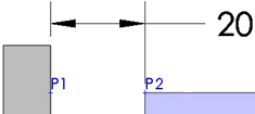
The reference points are placed directly opposite one another on the surfaces of the two planes.
|

|
Center, Minimum, and Maximum. Directs the measurement to the center or edge of the feature. These options are available when you select a feature-of-size.
Examples:
The minimum and maximum side options are supported for these feature types:
-
Boss
-
Cylinder
-
Notch
-
Simple Hole
-
Slot
-
Width
Measurement Direction
Sets the direction of the dimension when the measurement is applied between two axes (including slot axes).
X, Y, and Z. These options are relative to the coordinate system and are enabled for each axis that is perpendicular to the axes of the features.
N. Normal. Orients the dimension at the shortest distance normal to the two axes.
U. User defined. Orients the dimension along a selected line or normal to a selected planar face.
|
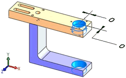
The example illustrates two measurements defined to evaluate the offset between two bearing bores, where one is defined along the X-axis and the other along the Z-axis.
|

|