Creating Drawings of Sheet Metal Parts
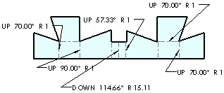
When you create a drawing of your sheet metal part, a flat pattern is automatically created. Drawings of sheet metal parts can also contain views of the bent sheet metal part.
 You can create *.dxf files of sheet metal flat patterns without creating a drawing.
To create a drawing of a flat pattern:
-
Open the sheet metal part for which you want to add a drawing.
-
Click Make Drawing from Part/Assembly  (Standard toolbar), and click OK to open the drawing sheet. (Standard toolbar), and click OK to open the drawing sheet.
-
Select a format or click OK to use the default format.
-
From the View Palette, drag the Flat pattern to the drawing sheet.
 You can adjust the size of the drawing view under Scale by selecting Use custom scale, and typing a value. You can adjust the size of the drawing view under Scale by selecting Use custom scale, and typing a value.
|
|
A flat pattern is displayed with sheet metal bend notes. You can set options for bend notes in Document Properties - Sheet Metal.
|

|
-
Click OK  . .
 If you want to toggle the suppression of additional features in a flat pattern, create a
part configuration of a flat pattern
, then select a drawing view for it. If you want to toggle the suppression of additional features in a flat pattern, create a
part configuration of a flat pattern
, then select a drawing view for it.
|
To toggle the visibility of the sheet metal bend notes:
-
Select the flat pattern drawing view to display the Drawing View PropertyManager.
-
Click More Properties.
-
In the View Properties tab, clear Display sheet metal bend notes.
 You can also right-click Drawing View
  in the FeatureManager design tree and select Properties.
To toggle the visibility of the bend lines:
 Hiding the bend lines also hides the sheet metal bend notes.
-
In the FeatureManager design tree, expand Drawing View to show the Flat-Pattern feature.
|
-
Expand the Flat-Pattern feature, right-click Bend-Lines and select Show or Hide.
|

|
To toggle the visibility of the bend region lines:
-
Right-click the drawing view in the drawing sheet.
|
-
Select Tangent Edge, Tangent Edges Visible, or Tangent Edges Removed.
- or -
Select Tangent Edge, Tangent Edges With Font to show bend region lines in the specified document Line Font.
 If the bend region lines do not appear, go back to the part window and right-click Flat-Pattern in the FeatureManager design tree. Select Edit Feature, and clear Merge faces. You may have to rebuild the drawing to see the tangent edges. If the bend region lines do not appear, go back to the part window and right-click Flat-Pattern in the FeatureManager design tree. Select Edit Feature, and clear Merge faces. You may have to rebuild the drawing to see the tangent edges.
|