Draft Analysis Overview
Designers of plastic parts and mold tooling manufacturers can use the Draft Analysis tool to check the correct application of draft to the faces of their part. With draft analysis, you can verify draft angles, examine angle changes within a face, as well as locate parting lines, injection, and ejection surfaces in parts.
 You can also perform draft analysis using the DraftXpert.
Criteria
To perform a draft analysis, specify the following criteria:
-
Direction of Pull. Select a planar face, linear edge, or an axis to define the draw direction. You can adjust the direction of pull by selecting Adjustment triad and dragging the triad.
-
Face classification. When selected, the analysis examines each face on the model, based on the draft angle. When you click Calculate, each face is displayed in a different color. With this option cleared, the analysis generates a contour map of the face angles.
NOTE: You must specify both the Direction of Pull and the Draft Angle with either type of analysis.
-
Reverse Direction  . Click to change the draw direction.
-
Draft Angle  . Enter a reference draft angle, and then compare that reference angle to those currently existing on the model.
Categories
The results displayed when you click Calculate depend on the type of draft analysis you select. Each time you change the type of analysis or the parameters, you need to re-calculate.
Face Classification
In the graphics area, each face displays a color based on the Draft angle you selected.
|
Draft analysis results listed under Color Settings are grouped into four categories, when you specify Face classification:
|
-
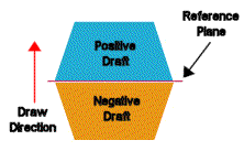
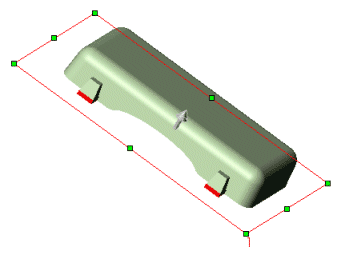
Positive draft. Displays any faces with a positive draft, based on the reference draft angle you specified. A positive draft means the angle of the face, with respect to the direction of pull, is more than the reference angle.
-
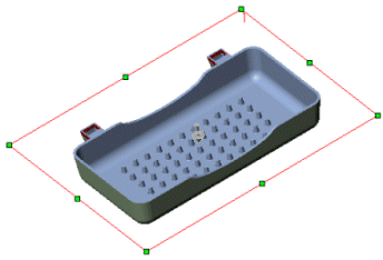
Negative draft. Displays any faces with a negative draft, based on the reference draft angle you specified. A negative draft means the angle of the face, with respect to the direction of the pull, is less than the negative reference angle.
-
Requires Draft. Displays any faces that require correction. These are faces with an angle greater than the negative reference angle, and less than the positive reference angle.
-
Straddle faces. Displays any faces that contain both positive and negative types of draft. Typically, these are faces that requires you to create a split line.
NOTE: Display colors may vary. The first time you use draft analysis, the system uses default colors. If you modify the colors, the system will use the new colors you specified.
|
|
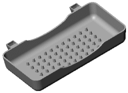
In the examples below, a draft analysis using Face classification was applied to the model.
|
|
|
|
No draft analysis applied
|
Positive draft
|
|
|
|
|
Negative draft
|
Draft required
|
Each category includes the following information and capability:
-
Number of faces included in the category, shown as the number on the color swatch for that category 
-
Toggle display using Show  or Hide
-
Change the default display colors
-
Save the color classifications with the part when you click  .
.
Find Steep Faces
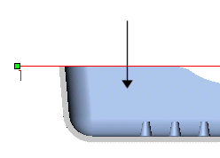
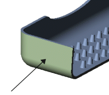
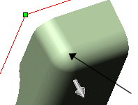
This option is used only to analyze the curved faces on a model where a draft was added. Based on the reference angle, there are points on a curved face that meet the criteria, and other points on the curve that do not meet the criteria specified by the reference angle. On some models that include curved faces, all areas along the curve may meet or exceed the reference angle. In such cases, selecting Find steep faces will not register any results, since any point along the curved face meets or exceeds the reference angle.
-
Positive steep faces. Displays any steep faces with a positive draft, based on the reference draft angle you specified.
-
Negative steep faces. Displays any steep faces with a negative draft, based on the reference draft angle you specified.
Surfaces
When analyzing the draft for surfaces, an additional Face classification criterion is added: Surface faces with draft. Since a surface includes an inside and an outside face, surface faces are not added to the numerical part of the classification (Positive draft and Negative draft). Surface faces with draft lists all positive and negative surfaces that include draft.
|
|
|
|
|
Negative draft
|
Positive draft
|
No steep faces, as all points along curved face are greater than the reference angle
|
Color Settings
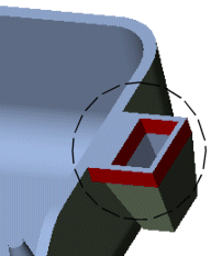
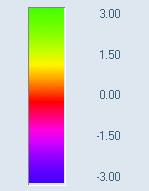
Clear Face classification to generate a color contour map. Color contour displays the uniform or graduated changes within each face on the model as the angle on the face changes. Based on the reference angle (Draft angle  ), the scale in the PropertyManager displays a positive to negative range, with 0 degrees at the center. You can select two display modes:
-
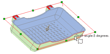
Uniform display. The uniform display uses three colors to represent the areas within the faces that have positive draft, negative draft, and that require draft. You can modify the three colors.
-
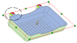
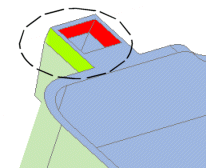
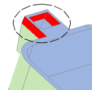
Transition display. Select the Gradual transition check box to display the variations in the angles on the model where the draft is required.
 You can see the individual faces of the model during a color contour calculation by specifying Shaded With Edges
  on the View toolbar.
The next time you analyze a model using color contour, these midrange values appear as the default.
NOTE: Using either display mode, move the pointer over an area on the model to display the value of the draft angle dynamically.
|
|
|
|
|
|
Gradual transition check box checked. Note the circled area.
|
|
|
|
|
|
Gradual transition check box cleared. Note the circled area.
|