Broken View
You can use a broken (or interrupted) view in a drawing. Broken views make it possible to display the drawing view in a larger scale on a smaller size drawing sheet. You create a gap or break in the view using a pair of break lines. Reference dimensions and model dimensions associated with the broken area reflect the actual model values.
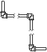
Broken views include the following functionality:
-
You can specify the gap between the break lines and the extension of the lines beyond the part geometry in Document Properties - Detailing.
-
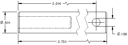
Dimensions that cross the break lines are broken automatically.
-
You can lock break lines in place. After breaking the view, dimension the break lines to a known portion of the geometry. These dimensions are only for use in the drawing document and do not appear on a printed drawing.

-
You can specify the line font for the break lines in Tools, Options, Document Properties, Line Font.
-
You can display dimension lines with a zig-zag by selecting Show dimensions as broken in broken views in Document Properties - Dimensions.
-
You can apply the Break View and Un-Break View commands to multiple views.
-
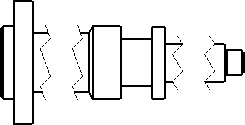
You can use multiple break lines in a view using any combination of horizontal or vertical break lines. All breaks use the same gap and break line style.
-
Broken views of flat pattern sheet metal parts include bend lines.
-
You can combine a broken view with one or more section views to create a rotated section (revolved section) view.
To create a broken view:
-
Select a drawing view and click Break  (Drawing toolbar) or click Insert, Drawing View, Break.
-
Set options in the PropertyManager:
-
Add vertical break line 
-
Add horizontal break line 
-
Gap size. Sets the amount of space between the gap.
-
Break line style  . Defines the type
of break line.
 In views with multiple breaks, the Break line style must be the same.
A break line attaches to the pointer.
-
Click in the view twice to place two break lines, creating the break.
The view is displayed with a gap in the geometry. In addition to model geometry, broken views also support cosmetic threads and axes.
-
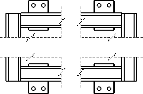
Add additional break lines as necessary. To create horizontal and vertical break lines in the same view, add multiple breaks using horizontal and vertical directions.
-
Click  .
.
To restore a broken view to its unbroken state:
Right-click the broken view, and select Un-Break View.
The break lines remain in the view and you can delete them.
To modify a broken view:
-
To change the shape of the break lines, right-click a break line and select a
from the shortcut menu.
-
To change the position of the break, drag the break lines.
-
To change the width of the break gap, select a break line and type a value in the PropertyManager.
 You can select an Area Hatch in a broken view only in its unbroken state. You cannot select an area hatch that crosses a break.
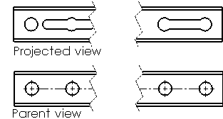
To align a break in a projected view with a break in the parent view:
-
Right-click in the projected view and click Properties.
-
In the dialog box, select Align breaks with parent.
-
Click OK.
|
|